Electrical Installation – Input/Output Wiring – Dual Mains
Punch 3 holes in the Conduit Box bottom to fit the size of the conduit pipes, and reattach the Conduit Box bottom to the Enclosure,
Install conduit pipes in the Conduit Box bottom.
Run cables through the conduit pipes and the bottom of the Conduit Box. Guide the cables behind the bar and up into the input/output area.
Reinstall the top part of the Conduit Box to the Enclosure, following reverse deinstallation procedures (described in a previous step).
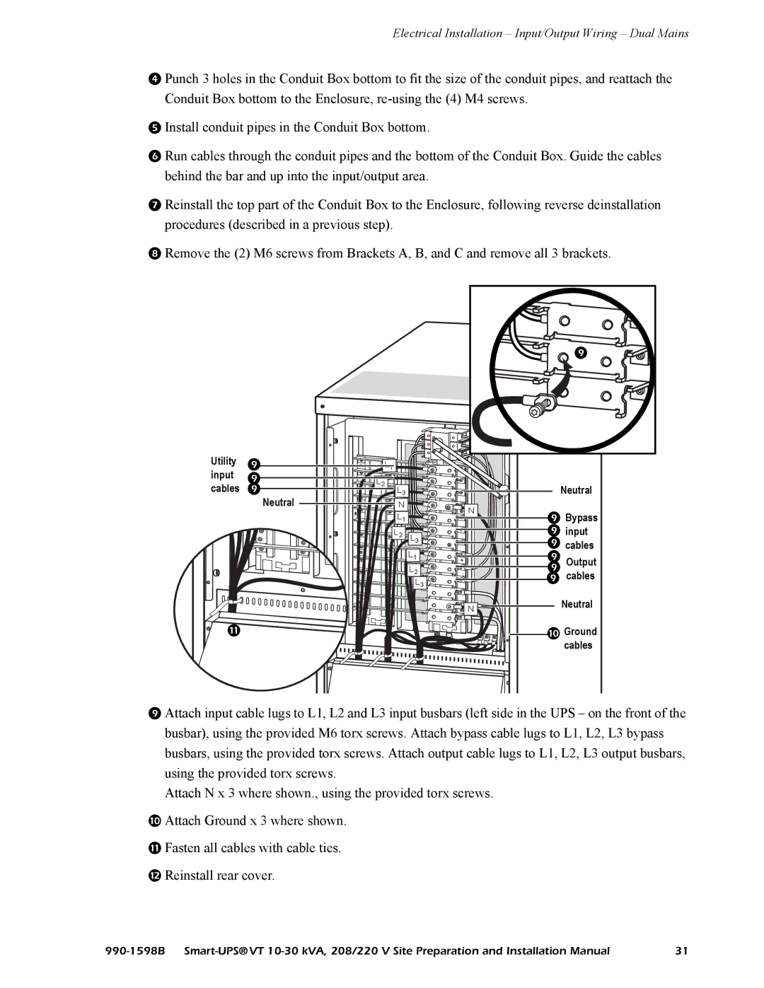
Remove the (2) M6 screws from Brackets A, B, and C and remove all 3 brackets.
Utility input cables Neutral
|
|
| |
L1 |
|
|
|
L2 | L3 |
| Neutral |
|
| ||
| N | N | Bypass |
| L1 | ||
|
| ||
| L2 | L3 | input |
|
| L1 | cables |
|
| Output | |
|
| L2 | |
|
| | |
|
| L3 | cables |
|
| N | Neutral |
![]()
![]()
![]() Groundcables
Groundcables
Attach input cable lugs to L1, L2 and L3 input busbars (left side in the UPS – on the front of the busbar), using the provided M6 torx screws. Attach bypass cable lugs to L1, L2, L3 bypass busbars, using the provided torx screws. Attach output cable lugs to L1, L2, L3 output busbars, using the provided torx screws.
Attach N x 3 where shown., using the provided torx screws.
Attach Ground x 3 where shown.
Fasten all cables with cable ties.
Reinstall rear cover.
31 |