Unit configuration menu: “Configuration”
6. Sensors and transducers
To access one of the parameters
displayed, press |
| and change |
value using | or | . Confirm the |
value by pressing |
| |
Temp probe |
| NTC |
Press probe |
| 4..20mA |
Min Press |
| 0.0bar |
Max Press |
| 30.0bar |
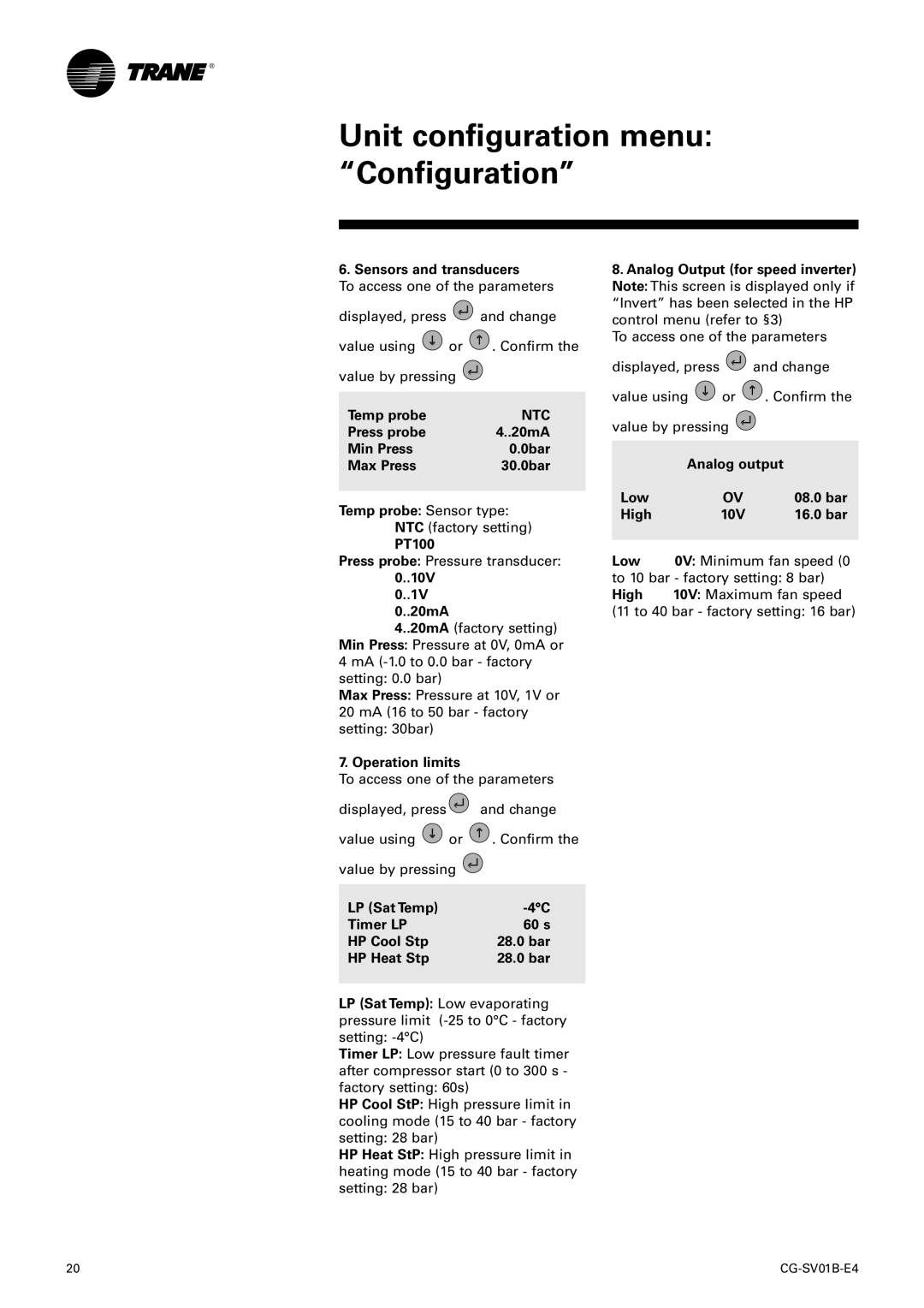
Temp probe: Sensor type: NTC (factory setting)
PT100
Press probe: Pressure transducer:
0..10V 0..1V 0..20mA
4..20mA (factory setting) Min Press: Pressure at 0V, 0mA or 4 mA
Max Press: Pressure at 10V, 1V or 20 mA (16 to 50 bar - factory setting: 30bar)
7. Operation limits
To access one of the parameters
displayed, press |
| and change |
value using | or | . Confirm the |
value by pressing |
| |
LP (Sat Temp) |
| |
Timer LP |
| 60 s |
HP Cool Stp |
| 28.0 bar |
HP Heat Stp |
| 28.0 bar |
LP (Sat Temp): Low evaporating pressure limit
Timer LP: Low pressure fault timer after compressor start (0 to 300 s - factory setting: 60s)
HP Cool StP: High pressure limit in cooling mode (15 to 40 bar - factory setting: 28 bar)
HP Heat StP: High pressure limit in heating mode (15 to 40 bar - factory setting: 28 bar)
8.Analog Output (for speed inverter) Note: This screen is displayed only if “Invert” has been selected in the HP control menu (refer to §3)
To access one of the parameters
displayed, press ![]() and change
and change
value using ![]() or
or ![]() . Confirm the value by pressing
. Confirm the value by pressing ![]()
| Analog output |
|
Low | OV | 08.0 bar |
High | 10V | 16.0 bar |
|
| |
Low | 0V: Minimum fan speed (0 | |
to 10 bar - factory setting: 8 bar) | ||
High | 10V: Maximum fan speed | |
(11 to 40 bar - factory setting: 16 bar)
20 |
