
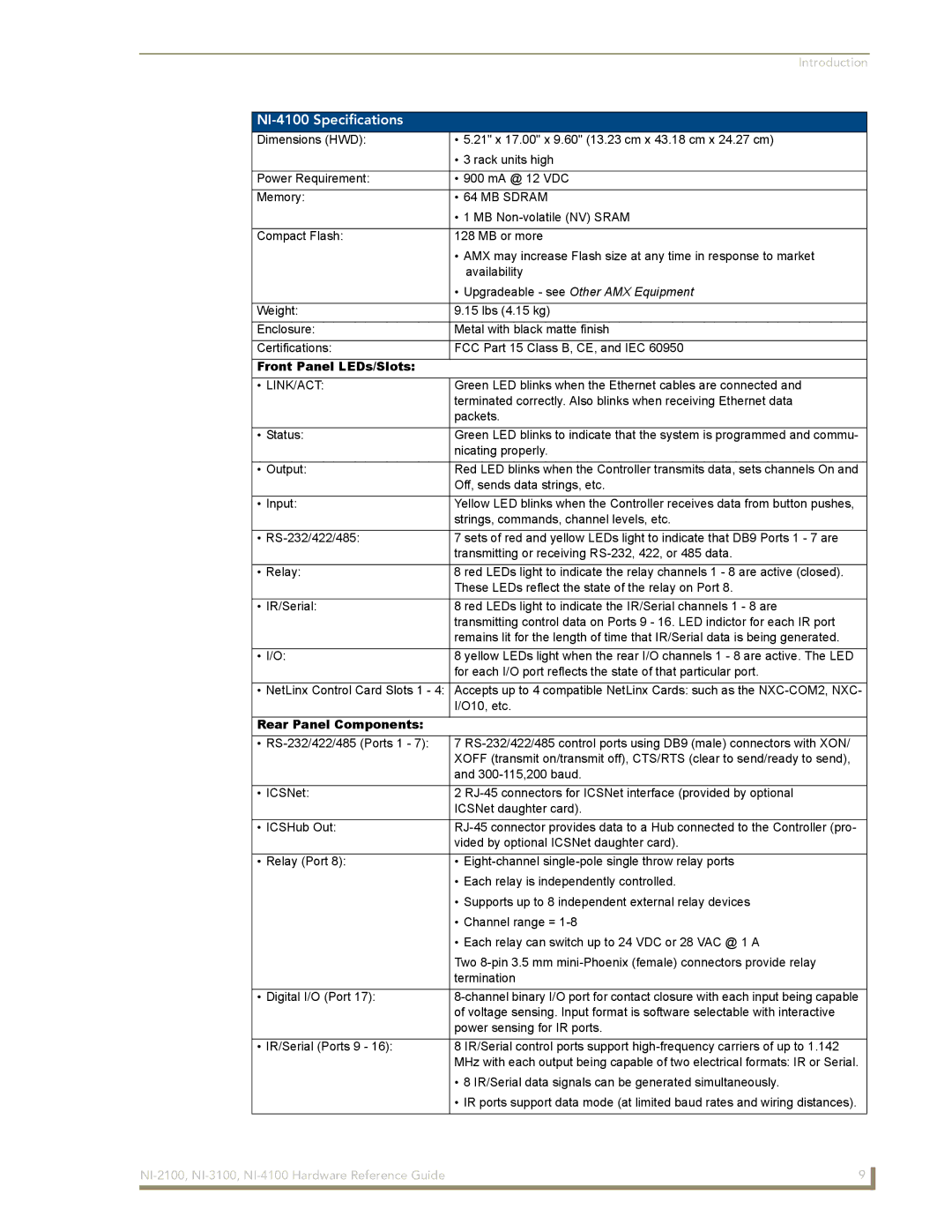
NI-2100, NI-3100, NI-4100 specifications
The AMX NI-4100, NI-2100, and NI-3100 are sophisticated, next-generation control systems designed to enhance the automation and management of audiovisual (AV) environments in various professional settings. These devices are built to streamline user interactions and improve overall efficiency in managing complex AV installations.The AMX NI-4100 stands as one of the most robust solutions in this lineup, featuring a powerful processor that can handle intensive processing tasks seamlessly. With its impressive memory capacity, the NI-4100 supports large-scale installations, making it ideal for corporate environments, educational institutions, and large auditoriums. This device operates on the latest version of the AMX control system software, ensuring compatibility with existing AV equipment. It also incorporates advanced networking capabilities, allowing for integration with multiple devices over an Ethernet network. The NI-4100 is equipped with numerous I/O ports, including multiple serial and IR outputs, offering extensive connectivity options for controlling various devices.
The AMX NI-3100, while slightly less powerful than the NI-4100, offers many essential features for small to medium-sized applications. It is designed with a focus on user experience, boasting an intuitive interface that simplifies operation for users. The NI-3100 supports the powerful AMX programming environment, which enables easy customization and programming of the control system to suit specific needs. Like its counterpart, the NI-3100 offers robust networking options and is capable of handling multiple device integrations, but in a more compact form factor. This makes it an excellent choice for conference rooms, huddle spaces, and education sectors where expertise in AV handling is not always present.
The AMX NI-2100 is the most compact model in the series, tailored for environments where space and budget considerations are paramount. Despite its smaller size, the NI-2100 shares many core functionalities seen in its larger counterparts. It maintains essential control features and reliable performance, making it suitable for smaller installations such as breakout rooms or smaller classrooms. The NI-2100 supports the same programming environment, ensuring it can be integrated into existing AMX solutions without compatibility issues.
All three models leverage AMX's innovative technology, allowing for seamless integration with a diverse range of third-party AV devices, enhancing the capability and scalability of any AV installation. They are also designed with security protocols to protect against unauthorized access, ensuring that the AV environments remain secure. Overall, the AMX NI-4100, NI-3100, and NI-2100 represent a complete suite of control solutions for varying AV needs, proving to be versatile assets in the modern multimedia landscape.