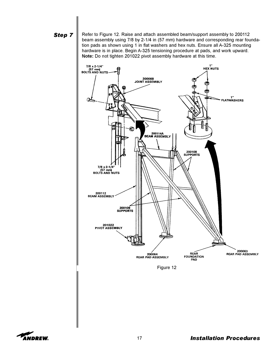
Andrew 9.3-Meter ESA manual Step, Installation Procedures

Models: 9.3-Meter ESA

1 66
Download 66 pages 32.87 Kb
Page 17
Image 17
Manual background

Step 7

Refer to Figure 12. Raise and attach assembled beam/support assembly to 200112 beam assembly using 7/8 by 2-1/4 in (57 mm) hardware and corresponding rear founda- tion pads as shown using 1 in flat washers and hex nuts. Ensure all A-325 mounting hardware is in place. Begin A-325 tensioning procedure at pads, and work upward. Note: Do not tighten 201022 pivot assembly hardware at this time.

Figure 12

17

Installation Procedures

Page 17
Image 17
Andrew 9.3-Meter ESA manual Step, Installation Procedures