Andrew 9.3-Meter ESA manual Panning Frame Assembly Step Step Step, Installation Procedures

Models: 9.3-Meter ESA

1 66
Download 66 pages 32.87 Kb
Page 18
Image 18
Panning Frame Assembly

Panning Frame Assembly

Step 1

Step 2

Step 3

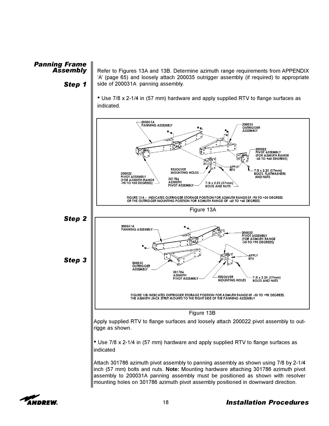
Refer to Figures 13A and 13B. Determine azimuth range requirements from APPENDIX ‘A’ (page 65) and loosely attach 200035 outrigger assembly (if required) to appropriate side of 200031A panning assembly.

Use 7/8 x 2-1/4 in (57 mm) hardware and apply supplied RTV to flange surfaces as indicated.

Figure 13A

Figure 13B

Apply supplied RTV to flange surfaces and loosely attach 200022 pivot assembly to out- rigge as shown.

Use 7/8 x 2-1/4 in (57 mm) hardware and apply supplied RTV to flange surfaces as indicated

Attach 301786 azimuth pivot assembly to panning assembly as shown using 7/8 by 2-1/4 inch (57 mm) bolts and nuts. Note: Mounting hardware attaching 301786 azimuth pivot assembly to 200031A panning assembly must be positioned as shown with resolver mounting holes on 301786 azimuth pivot assembly positioned in downward direction.

18

Installation Procedures

Page 18
Image 18
Andrew 9.3-Meter ESA manual Panning Frame Assembly Step Step Step, Installation Procedures