Andrew 9.3-Meter ESA manual Azimuth Jack Screw Assembly Step Step, Installation Procedures

Models: 9.3-Meter ESA

1 66
Download 66 pages 32.87 Kb
Page 22
Image 22
Azimuth Jack

Azimuth Jack

Screw Assembly

Step 1

Step 2

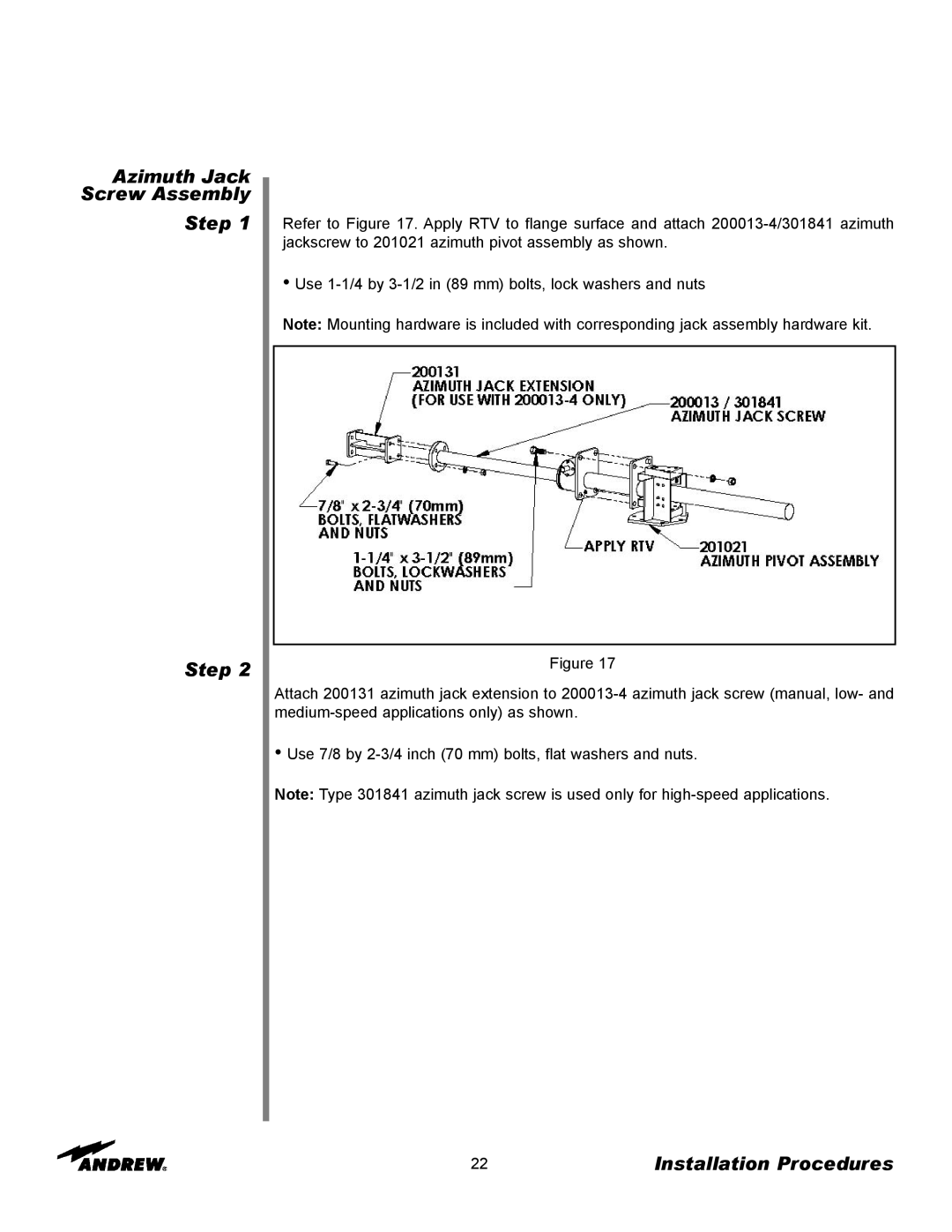
Refer to Figure 17. Apply RTV to flange surface and attach 200013-4/301841 azimuth jackscrew to 201021 azimuth pivot assembly as shown.

Use 1-1/4 by 3-1/2 in (89 mm) bolts, lock washers and nuts

Note: Mounting hardware is included with corresponding jack assembly hardware kit.

Figure 17

Attach 200131 azimuth jack extension to 200013-4 azimuth jack screw (manual, low- and medium-speed applications only) as shown.

Use 7/8 by 2-3/4 inch (70 mm) bolts, flat washers and nuts.

Note: Type 301841 azimuth jack screw is used only for high-speed applications.

22

Installation Procedures

Page 22
Image 22
Andrew 9.3-Meter ESA manual Azimuth Jack Screw Assembly Step Step, Installation Procedures