Step 2
Step 3
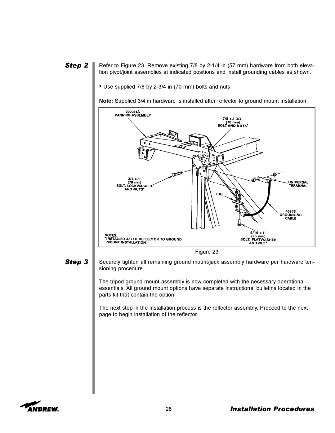
Refer to Figure 23. Remove existing 7/8 by
•Use supplied 7/8 by
Note: Supplied 3/4 in hardware is installed after reflector to ground mount installation.
Figure 23
Securely tighten all remaining ground mount/jack assembly hardware per hardware ten- sioning procedure.
The tripod ground mount assembly is now completed with the necessary operational essentials. All ground mount options have separate instructional bulletins located in the parts kit that contain the option.
The next step in the installation process is the reflector assembly. Proceed to the next page to begin installation of the reflector.
28 | Installation Procedures |