Preface
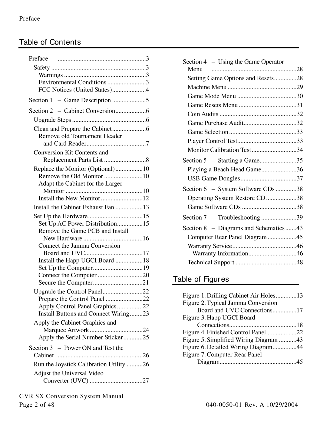
Table of Contents
Preface | ....................................................... | 3 |
Safety | 3 | |
Warnings | 3 | |
Environmental Conditions | 3 | |
FCC Notices (United States) | 4 | |
Section 1 | – Game Description | 5 |
Section 2 | – Cabinet Conversion | 6 |
Upgrade Steps | 6 | |
Clean and Prepare the Cabinet | 6 | |
Remove old Tournament Header |
| |
and Card Reader | 7 | |
Conversion Kit Contents and |
| |
Replacement Parts List | 8 | |
Replace the Monitor (Optional) | 10 | |
Remove the Old Monitor | 10 | |
Adapt the Cabinet for the Larger |
| |
Monitor | 10 | |
Install the New Monitor | 12 | |
Install the Cabinet Exhaust Fan | 13 | |
Set Up the Hardware | 15 | |
Set Up AC Power Distribution | 15 | |
Remove the Game PCB and Install |
| |
New Hardware | 16 | |
Connect the Jamma Conversion |
| |
Board and UVC | 17 | |
Install the Happ UGCI Board | 18 | |
Set Up the Computer | 19 | |
Connect the Computer | 20 | |
Secure the Computer | 21 | |
Upgrade the Control Panel | 22 | |
Prepare the Control Panel | 22 | |
Apply Control Panel Graphics | 22 | |
Install Buttons and Connect Wiring | 23 | |
Apply the Cabinet Graphics and |
| |
Marquee Artwork | 24 | |
Apply the Serial Number Sticker | 25 | |
Section 3 | – Power ON and Test the |
|
Cabinet | ..................................................... | 26 |
Run the Joystick Calibration Utility | 26 | |
Adjust the Universal Video |
| |
Converter (UVC) | 27 | |
GVR SX Conversion System Manual |
| |
Page 2 of 48 |
|
|
Section 4 | – Using the Game Operator |
|
Menu | ..................................................... | 28 |
Setting Game Options and Resets | 28 | |
Machine Menu | 29 | |
Game Mode Menu | 30 | |
Game Resets Menu | 31 | |
Coin Audits | 32 | |
Game Purchase Audit | 32 | |
Game Selection | 33 | |
Player Control Test | 33 | |
Monitor Calibration Test | 34 | |
Section 5 | – Starting a Game | 35 |
Playing a Beach Head Game | 36 | |
USB Game Dongles | 37 | |
Section 6 | – System Software CDs | 38 |
Operating System Restore CD | 38 | |
Game Software CDs | 38 | |
Section 7 | – Troubleshooting | 39 |
Section 8 | – Diagrams and Schematics | 43 |
Computer Rear Panel Diagram | 45 | |
Warranty Service | 46 | |
Warranty Information | 46 | |
Technical Support | 48 | |
Table of Figures |
| |
Figure 1. Drilling Cabinet Air Holes | 13 | |
Figure 2. Typical Jamma Conversion |
| |
Board and UVC Connections | 17 | |
Figure 3. Happ UGCI Board |
| |
Connections | 18 | |
Figure 4. Finished Control Panel | 22 | |
Figure 5. Simplified Wiring Diagram | 43 | |
Figure 6. Detailed Wiring Diagram | 44 | |
Figure 7. Computer Rear Panel |
| |
Diagram | 45 | |
