Section 2 – Cabinet Conversion
Connect the Computer
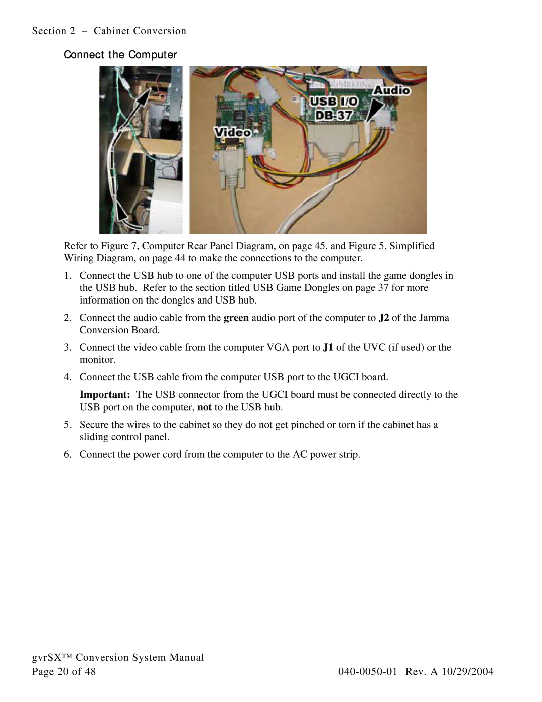
Refer to Figure 7, Computer Rear Panel Diagram, on page 45, and Figure 5, Simplified Wiring Diagram, on page 44 to make the connections to the computer.
1.Connect the USB hub to one of the computer USB ports and install the game dongles in the USB hub. Refer to the section titled USB Game Dongles on page 37 for more information on the dongles and USB hub.
2.Connect the audio cable from the green audio port of the computer to J2 of the Jamma Conversion Board.
3.Connect the video cable from the computer VGA port to J1 of the UVC (if used) or the monitor.
4.Connect the USB cable from the computer USB port to the UGCI board.
Important: The USB connector from the UGCI board must be connected directly to the USB port on the computer, not to the USB hub.
5.Secure the wires to the cabinet so they do not get pinched or torn if the cabinet has a sliding control panel.
6.Connect the power cord from the computer to the AC power strip.
gvrSX™ Conversion System Manual |
|
Page 20 of 48 |