Section 2 – Cabinet Conversion
4.Place the joystick direction sticker over the joystick hole. Make sure that it is properly aligned with the cabinet and monitor and then peel off the backing and apply the sticker. If the sticker has protective paper over the face, wet the paper and wait about 15 minutes before removing it to avoid damaging the artwork.
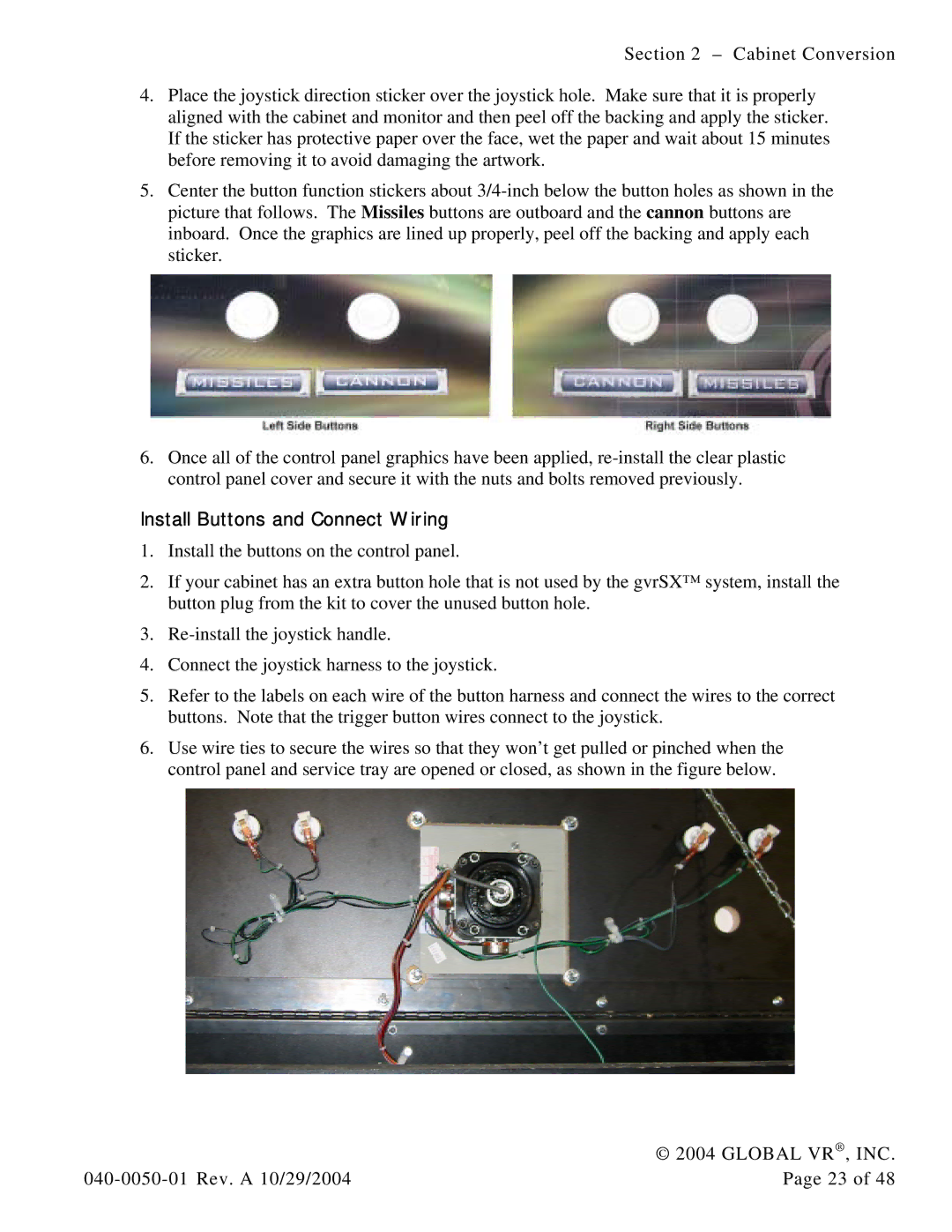
5.Center the button function stickers about
6.Once all of the control panel graphics have been applied,
Install Buttons and Connect Wiring
1.Install the buttons on the control panel.
2.If your cabinet has an extra button hole that is not used by the gvrSX™ system, install the button plug from the kit to cover the unused button hole.
3.
4.Connect the joystick harness to the joystick.
5.Refer to the labels on each wire of the button harness and connect the wires to the correct buttons. Note that the trigger button wires connect to the joystick.
6.Use wire ties to secure the wires so that they won’t get pulled or pinched when the control panel and service tray are opened or closed, as shown in the figure below.
| © 2004 GLOBAL VR®, INC. |
Page 23 of 48 |