Enabling SIPI
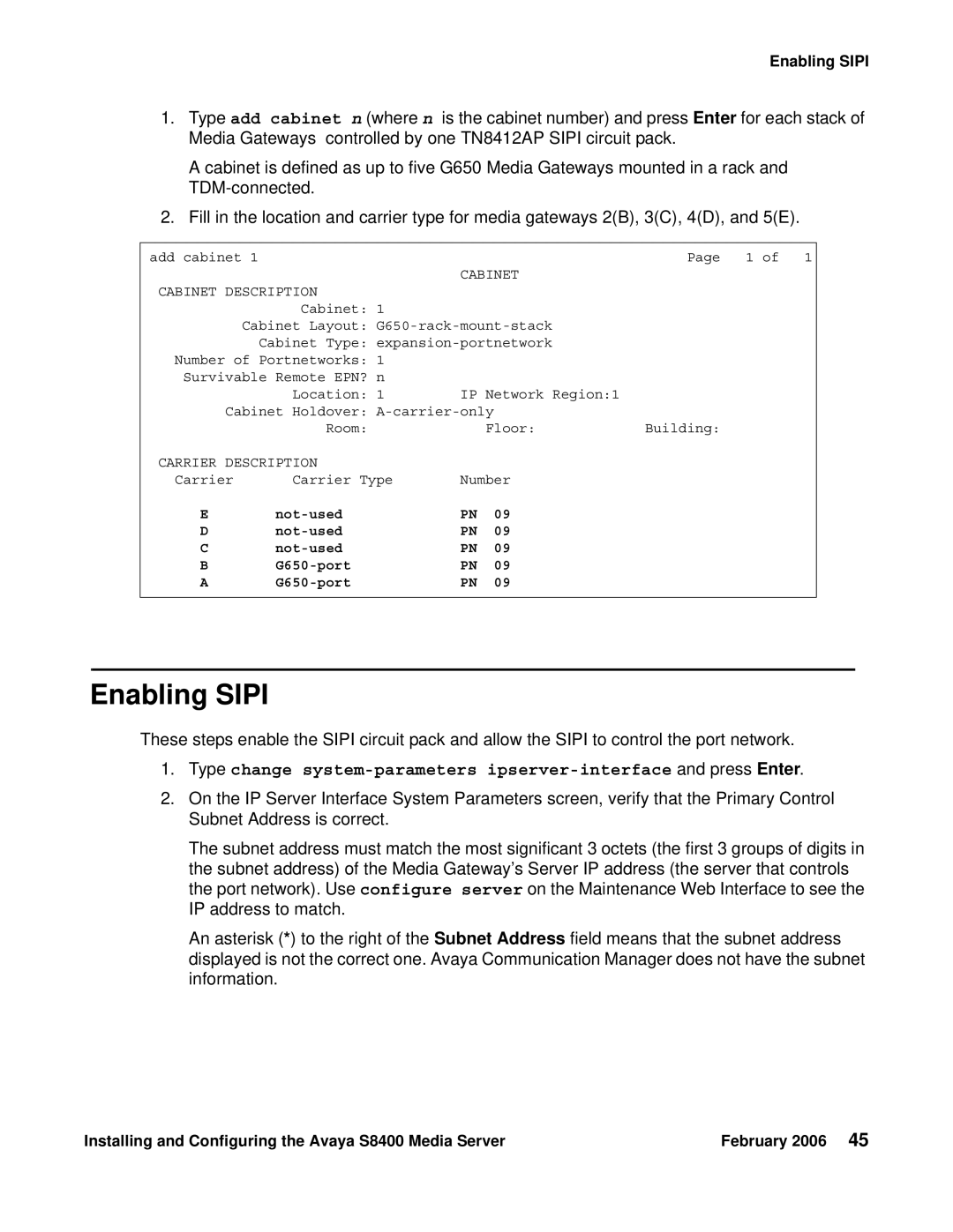
1.Type add cabinet n (where n is the cabinet number) and press Enter for each stack of Media Gateways controlled by one TN8412AP SIPI circuit pack.
A cabinet is defined as up to five G650 Media Gateways mounted in a rack and
2.Fill in the location and carrier type for media gateways 2(B), 3(C), 4(D), and 5(E).
add cabinet 1 |
|
| Page 1 of 1 |
|
| CABINET |
|
CABINET DESCRIPTION |
|
|
|
Cabinet: | 1 |
|
|
Cabinet Layout: |
| ||
Cabinet Type: |
| ||
Number of Portnetworks: | 1 |
|
|
Survivable Remote EPN? | n |
|
|
Location: | 1 | IP Network Region:1 |
|
Cabinet Holdover: |
| ||
Room: |
| Floor: | Building: |
CARRIER DESCRIPTION |
|
| |
Carrier | Carrier Type | Number | |
E | PN | 09 | |
D | PN | 09 | |
C | PN | 09 | |
B | PN | 09 | |
A | PN | 09 | |
Enabling SIPI
These steps enable the SIPI circuit pack and allow the SIPI to control the port network.
1.Type change
2.On the IP Server Interface System Parameters screen, verify that the Primary Control Subnet Address is correct.
The subnet address must match the most significant 3 octets (the first 3 groups of digits in the subnet address) of the Media Gateway’s Server IP address (the server that controls the port network). Use configure server on the Maintenance Web Interface to see the IP address to match.
An asterisk (*) to the right of the Subnet Address field means that the subnet address displayed is not the correct one. Avaya Communication Manager does not have the subnet information.
Installing and Configuring the Avaya S8400 Media Server | February 2006 45 |