1.9 Calibration
Don’t Perform Calibrate Until You Really Understand.
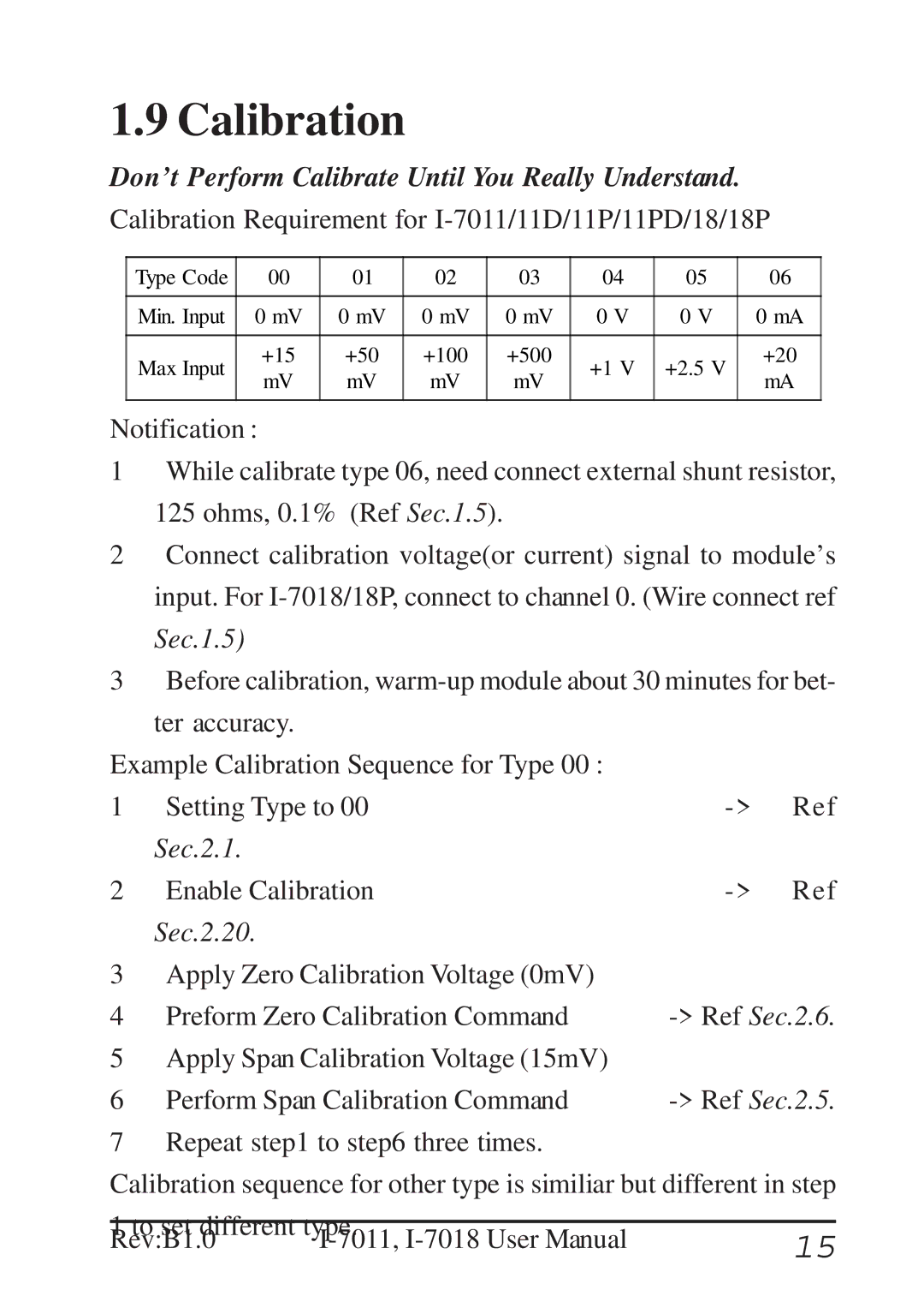
Calibration Requirement for
Type Code | 00 | 01 | 02 | 03 | 04 | 05 | 06 | |
|
|
|
|
|
|
|
| |
Min. Input | 0 mV | 0 mV | 0 mV | 0 mV | 0 V | 0 V | 0 mA | |
|
|
|
|
|
|
|
| |
Max Input | +15 | +50 | +100 | +500 | +1 V | +2.5 V | +20 | |
mV | mV | mV | mV | mA | ||||
|
|
| ||||||
|
|
|
|
|
|
|
|
Notification :
1While calibrate type 06, need connect external shunt resistor, 125 ohms, 0.1% (Ref Sec.1.5).
2Connect calibration voltage(or current) signal to module’s input. For
3Before calibration,
Example Calibration Sequence for Type 00 : |
|
| |
1 | Setting Type to 00 | Ref | |
| Sec.2.1. |
|
|
2 | Enable Calibration | Ref | |
| Sec.2.20. |
|
|
3 | Apply Zero Calibration Voltage (0mV) |
|
|
4 | Preform Zero Calibration Command | ||
5 | Apply Span Calibration Voltage (15mV) |
|
|
6 | Perform Span Calibration Command |
| |
7 | Repeat step1 to step6 three times. |
|
|
Calibration sequence for other type is similiar but different in step
1 to set different type. | 15 | |
Rev:B1.0 | ||
