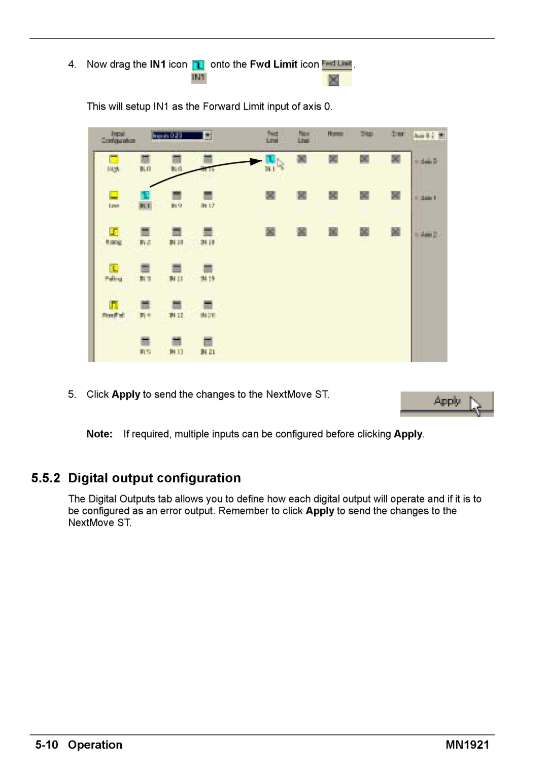
4.Now drag the IN1 icon ![]() onto the Fwd Limit icon
onto the Fwd Limit icon ![]() . This will setup IN1 as the Forward Limit input of axis 0.
. This will setup IN1 as the Forward Limit input of axis 0.
5. Click Apply to send the changes to the NextMove ST.
Note: If required, multiple inputs can be configured before clicking Apply.
5.5.2 Digital output configuration
The Digital Outputs tab allows you to define how each digital output will operate and if it is to be configured as an error output. Remember to click Apply to send the changes to the NextMove ST.
MN1921 |