Servicing Information
V.11 / X.21 Link Pinouts
| X.21 |
| Direction | |
Contact | Circuits | Circuit | To | From |
No. | Ref. | Name | DCE | DCE |
1 |
| Protective Ground | NA | |
|
|
|
|
|
2 | T (A) | Transmitted Data (A) | X |
|
|
|
|
|
|
3 | C (A) | Control (A) | X |
|
|
|
|
|
|
4 | R (A) | Received Data (A) |
| X |
|
|
|
|
|
5 | I (A) | Indication (A) |
| X |
6 | S (A) | Signal Element Timing (A) |
| X |
7 |
|
|
| |
8 | Ground | Signal Ground | NA | |
9 | T (B) | Transmitted Data (B) | X |
|
10 | C (B) | Control (B) | X |
|
11 | R (B) | Received Data (B) |
| X |
12 | I (B) | Indication (B) |
| X |
13 | S (B) | Signal Element Timing (B) |
| X |
|
|
|
|
|
14 |
|
|
| |
|
|
|
|
|
15 |
|
|
| |
|
|
|
|
|
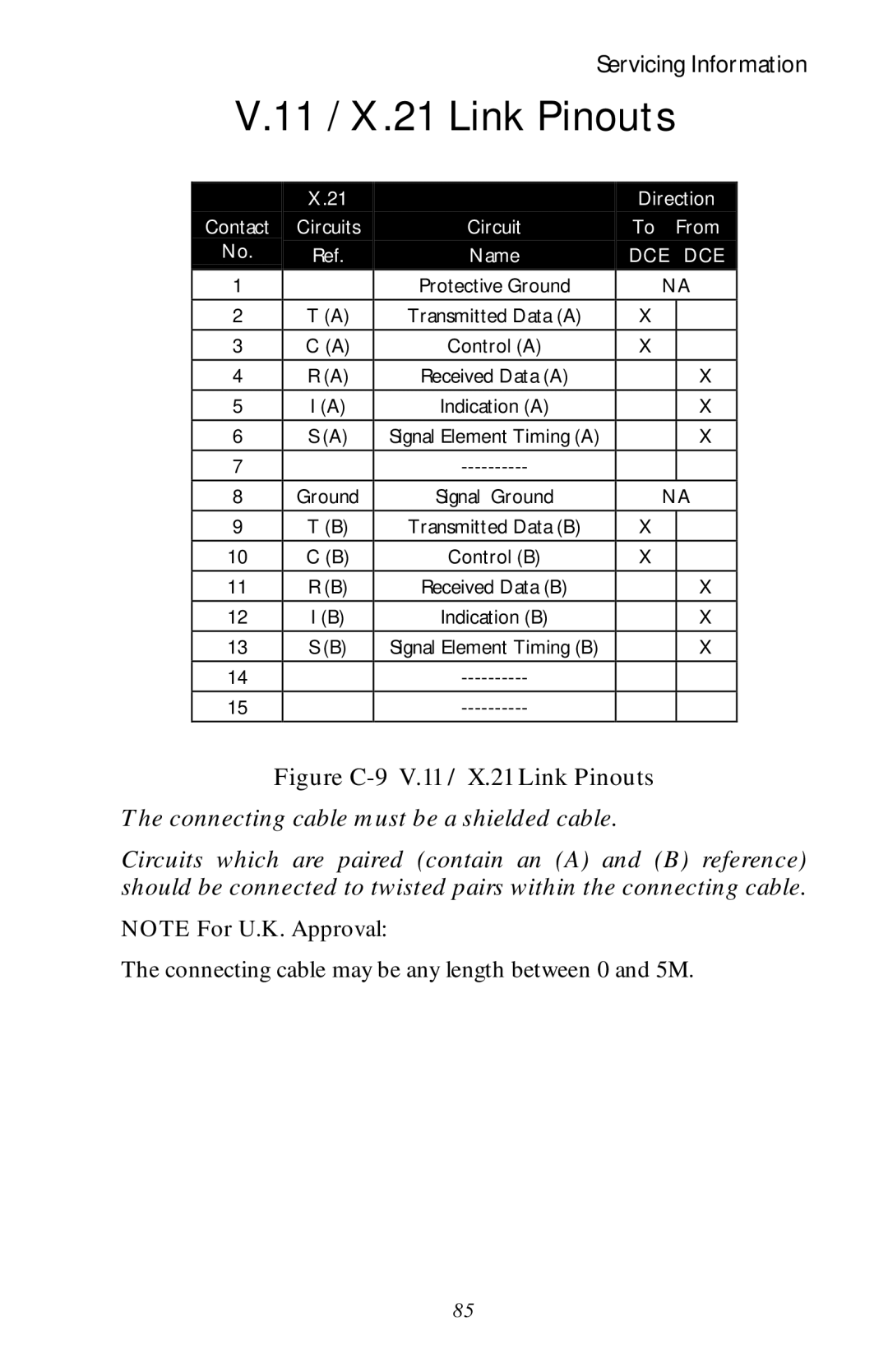
Figure C-9 V.11 / X.21 Link Pinouts
The connecting cable must be a shielded cable.
Circuits which are paired (contain an (A) and (B) reference) should be connected to twisted pairs within the connecting cable.
NOTE For U.K. Approval:
The connecting cable may be any length between 0 and 5M.
85