MIC400 Series Camera Installation and Operation Manual
Boot Messages
The large square text box in this area will display boot messages coming from the MIC. One of the first lines contains the MIC address which is decoded and entered into the Address line. The rest of the lines indicate the MIC model number, control card serial number, MIC Software etc.
At the same time, a boot message is displayed on the video indicating similar information, which may be helpful if return comms should fail or be incorrectly connected.
MIC Settings
Current Address
This box indicates the address to which commands are sent from Camset. This therefore needs to match the address of the MIC that needs to be controlled.
EN 31
When the MIC is booted the first line of the messages it sends is the address, which is read and put into this box automatically.
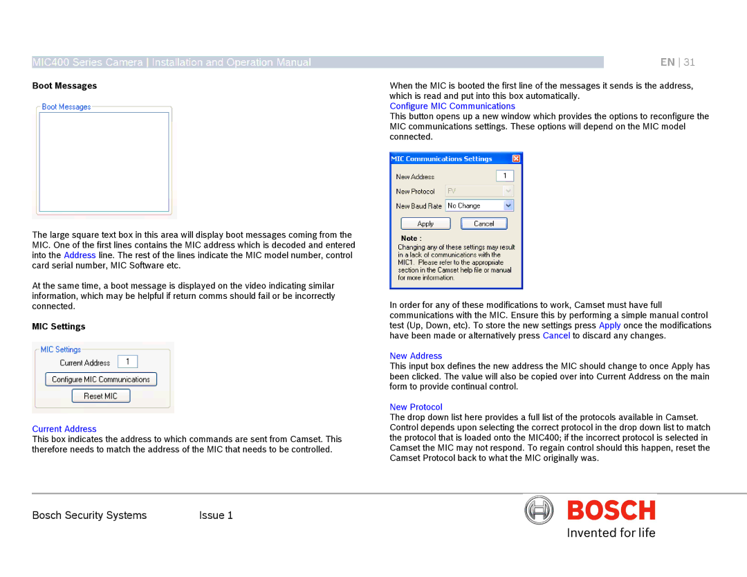
Configure MIC Communications
This button opens up a new window which provides the options to reconfigure the MIC communications settings. These options will depend on the MIC model connected.
In order for any of these modifications to work, Camset must have full communications with the MIC. Ensure this by performing a simple manual control test (Up, Down, etc). To store the new settings press Apply once the modifications have been made or alternatively press Cancel to discard any changes.
New Address
This input box defines the new address the MIC should change to once Apply has been clicked. The value will also be copied over into Current Address on the main form to provide continual control.
New Protocol
The drop down list here provides a full list of the protocols available in Camset. Control depends upon selecting the correct protocol in the drop down list to match the protocol that is loaded onto the MIC400; if the incorrect protocol is selected in Camset the MIC may not respond. To regain control should this happen, reset the Camset Protocol back to what the MIC originally was.
Bosch Security Systems | Issue 1 |