32

H

Dispenser Operation

2

1

Fig. 8-1

The Dispenser Assembly operates via a PTC Actuator (wax motor), item 1.

When voltage is applied to the Actuator it advances a Combination Lever, item 2.

The Combination Lever allows the Soap Door to open, and later in the cycle dispenses the Rinse Agent.

To remove the Actuator, first disconnect the Wiring Connector. Then, using a small screwdriver, release the locking tab….

1

2

Fig. 8-2

…and bring the Actuator out from the Dispenser.

Please note: The Combination Lever cannot be replaced individually, but only as part of a new Dispenser Assembly.
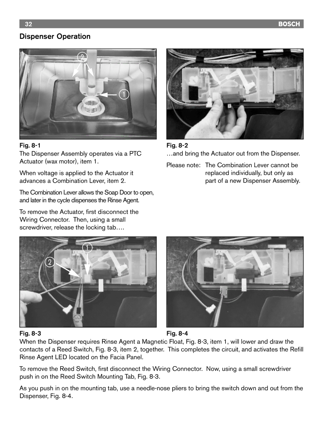
Fig. 8-3Fig. 8-4

When the Dispenser requires Rinse Agent a Magnetic Float, Fig. 8-3, item 1, will lower and draw the contacts of a Reed Switch, Fig. 8-3, item 2, together. This completes the circuit, and activates the Refill Rinse Agent LED located on the Facia Panel.

To remove the Reed Switch, first disconnect the Wiring Connector. Now, using a small screwdriver push in on the Reed Switch Mounting Tab, Fig. 8-3.

As you push in on the mounting tab, use a needle-nose pliers to bring the switch down and out from the Dispenser, Fig. 8-4.

Page 34
Image 34
Bosch Appliances 4302, TRUE, 6806, 6805, 4306, 6802 manual Dispenser Operation