Manuals
/
Bosch Appliances
/
Kitchen Appliance
/
Dishwasher
Bosch Appliances
6805, TRUE, 6806, 4306, 4302, 6802
manual
Water Level
Models:
6802
4302
4306
6805
6806
TRUE
1
26
87
87
Download
87 pages
49.01 Kb
23
24
25
26
27
28
29
30
Install
Cycle Chart
Timer u
Wiring Connectors I5
Left Side Access
Facia Assembly
Power Scrub Regular Delicate
Service Reminder Description
Interior Features
ON/OFF Switch Removal
Page 26
Image 26
24
H
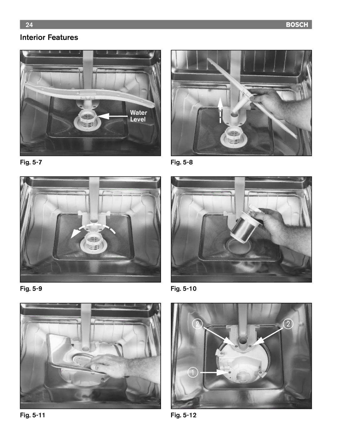
Interior Features
Water
Level
Fig.
5-7
Fig.
5-9
Fig.
5-8
Fig.
5-10
2 2
1
Fig.
5-11
Fig.
5-12
Page 25
Page 27
Page 26
Image 26
Page 25
Page 27
Contents
Bosch
Introduction
Table of Contents
SHV
Service Reminder Description
SHI
Section
Warranty / Technical Specifications
Customer Service Technical Service
Model / Serial Number Location
Product Overview
NTC
Product Overview
Page
Section
Operation
Cycle Chart
24.75 20.25
To Cancel a Cycle
To Operate
Type of dishware China Pots/pans
SHU 5302/5304/5305/5306/5312/5314/5315/5316
3.8 2.5 26.9/18.9 22.7/15.9 20.4/14.4 13.5/9.5 0.8 3.2
7Fig
Power Scrub Regular Delicate
Page
Section
Rack System
Rack System
Interior Features
Interior Features
Water Level
Interior Features
Detergent / Rinse-Agent Dispenser
Drying
Washability / Drying
Washability
HOW this System Functions
Service Reminder
Outer Door Removal Door Components Dispenser Operation
Outer Door Removal
Door Compoments
Dispenser Operation
To Remove
To Install
Dispenser Removal
Facia Assembly Removal
Facia Assembly
Important Service Note
Control Unit Removal
ON/OFF Switch Removal
Door Latch Assembly Removal
Page
Section
Base Components Front Accessible
= 7 8 2 9 =
Base Components Front Accessible
Base Components Front Accessible
Cut Away View
Service Reminder
Section
Left Side Access
Left Side Panel Removal
Left Side Components
Water Inlet / Discharge System Operation
Draining
Filling
Code
Water Inlet / Discharge System Removal
Section
Right Side Access
Right Side Panel Removal
Right Side Components
Component Explanation
NTC Operation
NTC Removal
NTC Removal
NTC Removal
NTC Removal
NTC is held in place by two locking tabs, items 1
Page
Section
Tank Removal
Tank Removal
Tank Removal
Base Components
Circulation Pump / Motor Removal
Circulation Pump / Motor Assembly
Circulation Pump / Motor Removal
Heater Assembly Removal
Heater Assembly
Heater Assembly Removal
Aqua Sensor
Door Spring Removal
To Replace the Springs
Page
Section
Diagram
SHI/U 43- Models
Diagram
Timer u
Power Scrub
Flow Switch Circulation Motor Economy
BKBU-f4 BU-l6-4 GY-l6-1 BNBK-b-3
Economy
NTC
Control Unit l2 Ground PE
Wiring Connectors I5
Control Unit Reed Switch e3
185˚F
On/Off Switch a1 Door Switch e0
BSH Home Appliances
Top
Page
Image
Contents