38 | H |
Base Components – Front Accessible
= 7 8 2 9 =
3 | 6 | 5 | 4 | 1 | 3 | |
|
|
|
|
| ||
|
|
|
|
|
|
|
Fig. |
|
|
|
|
|
|
|
|
|
|
| 2 | |
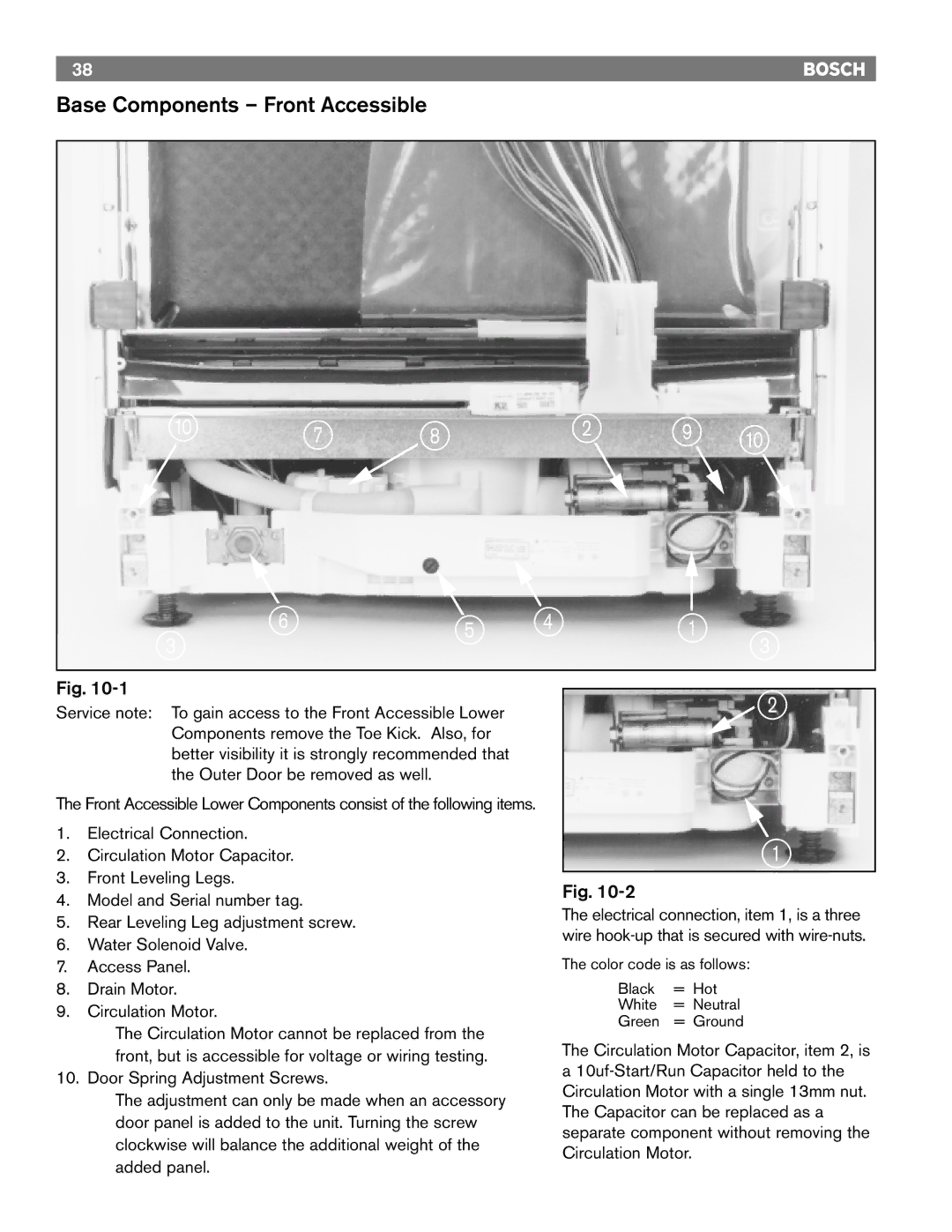
Service note: To gain access to the Front Accessible Lower |
|
|
| |||
Components remove the Toe Kick. Also, for |
|
|
|
| ||
better visibility it is strongly recommended that |
|
|
|
| ||
the Outer Door be removed as well. |
|
|
|
|
| |
The Front Accessible Lower Components consist of the following items.
1. | Electrical Connection. | 1 |
2. | Circulation Motor Capacitor. |
3.Front Leveling Legs.
4. | Model and Serial number tag. | Fig. |
| |
The electrical connection, item 1, is a three | ||||
5. | Rear Leveling Leg adjustment screw. | |||
wire | ||||
6. | Water Solenoid Valve. | |||
|
| |||
7. | Access Panel. | The color code is as follows: | ||
8. | Drain Motor. | Black | = Hot | |
9. | Circulation Motor. | White | = Neutral | |
Green | = Ground | |||
|
| |||
The Circulation Motor cannot be replaced from the | The Circulation Motor Capacitor, item 2, is | |
front, but is accessible for voltage or wiring testing. | ||
a | ||
10. Door Spring Adjustment Screws. | ||
Circulation Motor with a single 13mm nut. | ||
The adjustment can only be made when an accessory | ||
The Capacitor can be replaced as a | ||
door panel is added to the unit. Turning the screw | ||
separate component without removing the | ||
clockwise will balance the additional weight of the | ||
Circulation Motor. | ||
added panel. | ||
|