|
| e3 | NTC | 2 e1 | |
|
|
|
| ||
|
|
| f2 |
| 1 |
|
|
|
|
| 4 |
X2 | 1 | 1 |
| 1M | m2 |
|
|
|
| ||
|
|
| 2 | 1 |
|
12.6 | 12.8 | ||||
| |||||
|
|
|
|
| |
|
|
|
|
| |
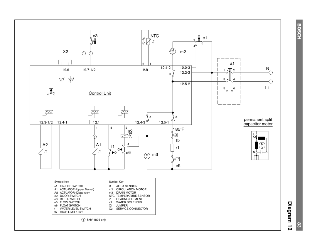
Control Unit
12.1 |
|
| ||||
|
| 1 | 3 |
| 2 | 185˚F |
|
|
|
|
| s2 | |
|
|
|
|
|
| |
|
| 1 |
|
|
| f5 |
A2 |
| A1 |
|
| 4 | |
| f1 | 2 | r1 | |||
|
|
|
| e6 | ||
|
|
|
| 1 | m3 | |
|
|
|
|
| 1M | |
|
|
|
|
|
| P |
|
|
|
|
|
| e5 |
Symbol Key |
| Symbol Key |
|
| ||
a1 | ON/OFF SWITCH |
| l4 | AQUA SENSOR |
| |
A1 | ACTUATOR (Upper Basket) | m2 | CIRCULATION MOTOR |
| ||
A2 | ACTUATOR (Dispenser) | m3 | DRAIN MOTOR |
| ||
e0 | DOOR SWITCH |
| NTC TEMPERATURE SENSOR |
| ||
e3 | REED SWITCH |
| r1 | HEATING ELEMENT |
| |
e5 | FLOW SWITCH |
| s2 | WATER SOLENOID |
| |
e6 | FLOAT SWITCH |
| X1 | JUMPER |
| |
f1 | WATER LEVEL SWITCH | X2 | SERVICE CONNECTOR |
| ||
f5 | HIGH LIMIT 185˚F |
|
|
|
|
|
| 1 | SHV 4803 only |
|
|
|
|
a1
12
3![]() 4
4
56
N
L1
permanent split capacitor motor
L ![]()
1M
N ![]()
![]()
![]()
H
Diagram 12 | 83 |