H
Fig.
CIRCULATION PUMP / MOTOR REMOVAL:
65
Circulation Pump / Motor Assembly
Fig.
Disconnect the four wire leads, then grasp the Circulation Motor and turn clockwise a quarter turn until the Motor stops, Fig.
Note: The Front Pump Housing remains in place when the Motor is removed,
With the Motor / Rear Pump Assembly removed from the unit, separate the Motor from the Rear Pump Assembly. To do so, first remove the Impeller by placing a block in the rear of the Motor and then turning the Impeller
The Rear Pump Assembly consists of four components, Fig.
1. | Rear Pump Housing. | 3. | Impeller. |
2. | Main Pump Seal. | 4. | Impeller Seal. |
Each component can be replaced as an individual item.
TO INSTALL:
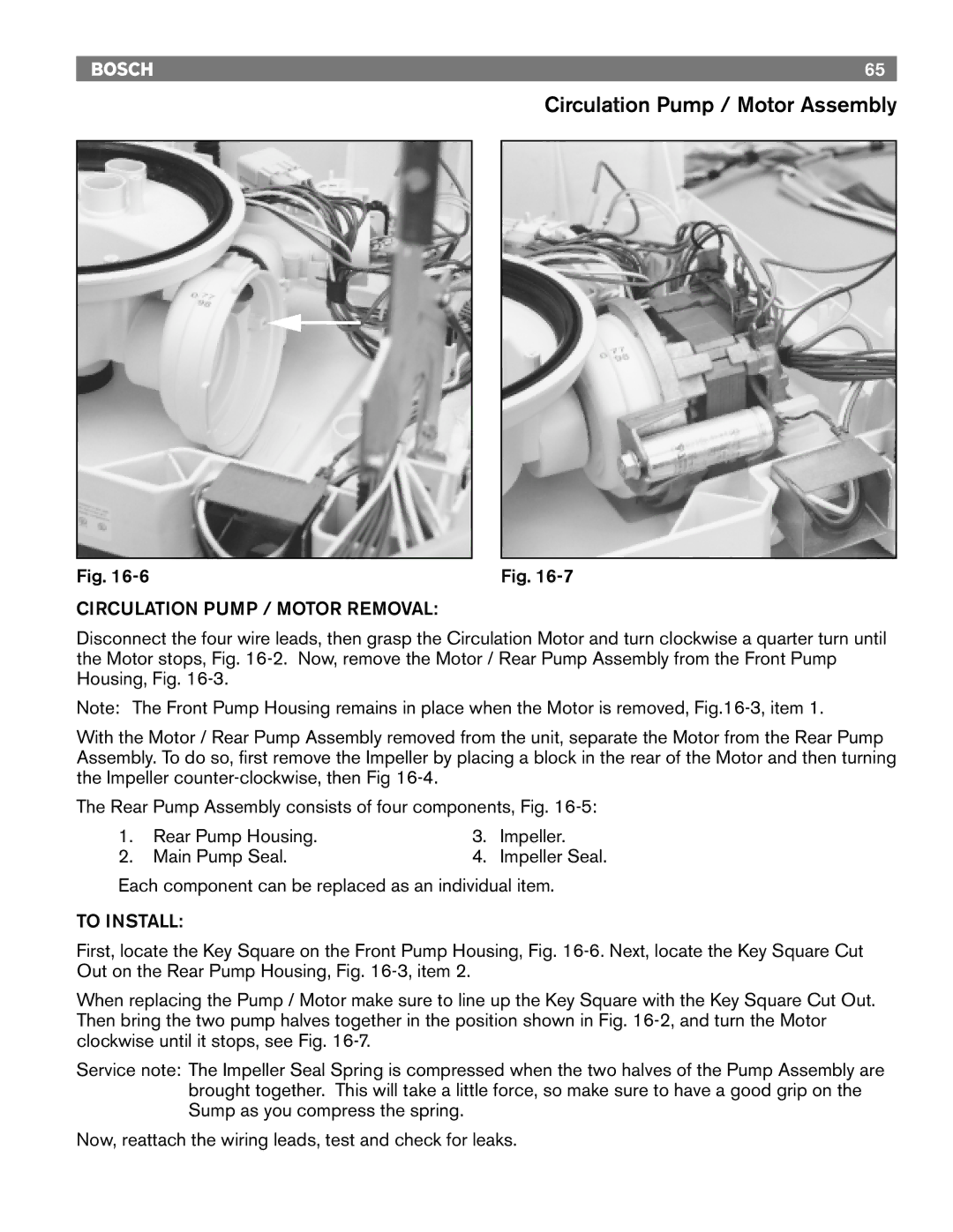
First, locate the Key Square on the Front Pump Housing, Fig.
When replacing the Pump / Motor make sure to line up the Key Square with the Key Square Cut Out. Then bring the two pump halves together in the position shown in Fig.
Service note: The Impeller Seal Spring is compressed when the two halves of the Pump Assembly are brought together. This will take a little force, so make sure to have a good grip on the Sump as you compress the spring.
Now, reattach the wiring leads, test and check for leaks.
