H | 51 |
Right Side Components
5
4
1
3
2
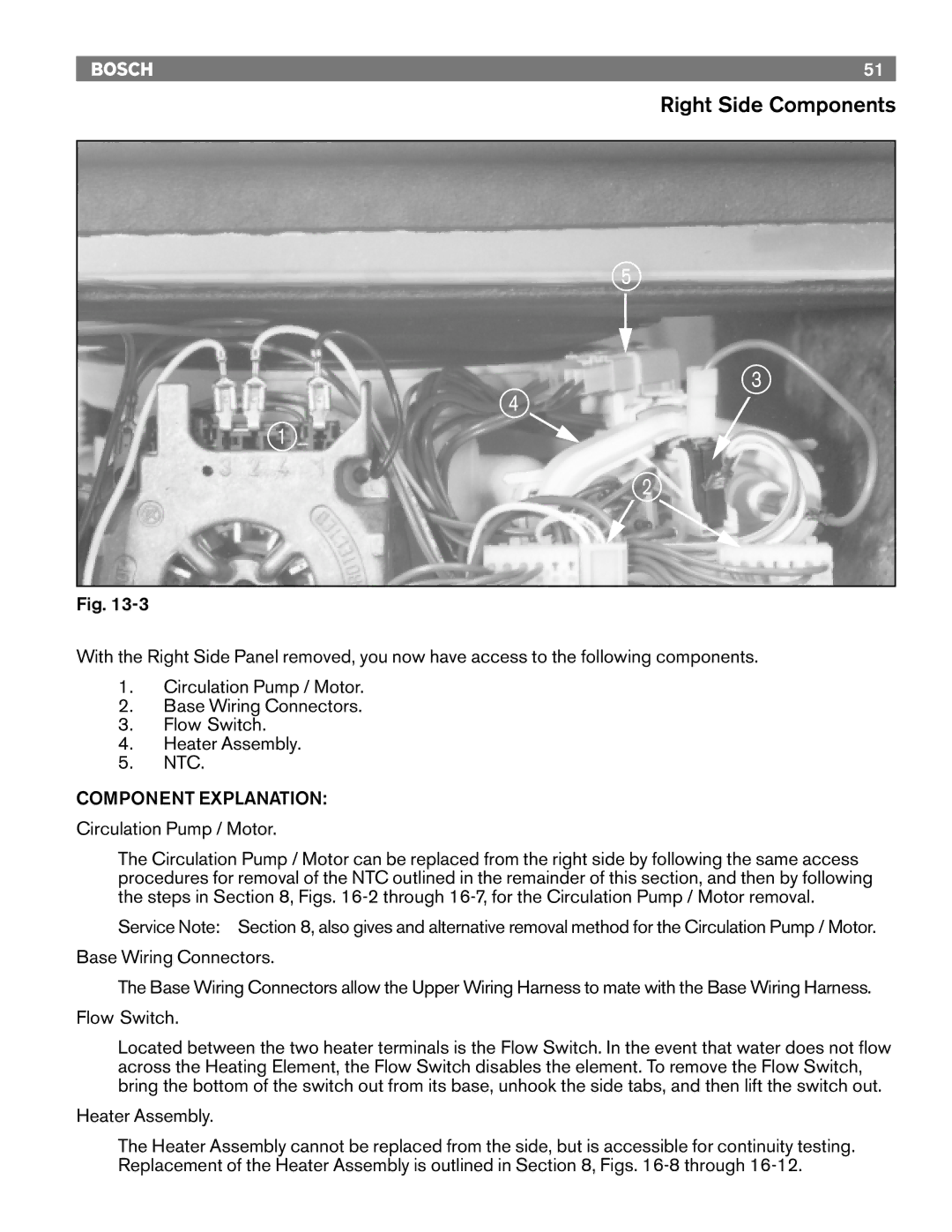
Fig.
With the Right Side Panel removed, you now have access to the following components.
1.Circulation Pump / Motor.
2.Base Wiring Connectors.
3.Flow Switch.
4.Heater Assembly.
5.NTC.
COMPONENT EXPLANATION:
Circulation Pump / Motor.
The Circulation Pump / Motor can be replaced from the right side by following the same access procedures for removal of the NTC outlined in the remainder of this section, and then by following the steps in Section 8, Figs.
Service Note: Section 8, also gives and alternative removal method for the Circulation Pump / Motor.
Base Wiring Connectors.
The Base Wiring Connectors allow the Upper Wiring Harness to mate with the Base Wiring Harness.
Flow Switch.
Located between the two heater terminals is the Flow Switch. In the event that water does not flow across the Heating Element, the Flow Switch disables the element. To remove the Flow Switch, bring the bottom of the switch out from its base, unhook the side tabs, and then lift the switch out.
Heater Assembly.
The Heater Assembly cannot be replaced from the side, but is accessible for continuity testing. Replacement of the Heater Assembly is outlined in Section 8, Figs.
