Network Management Options | 1 |
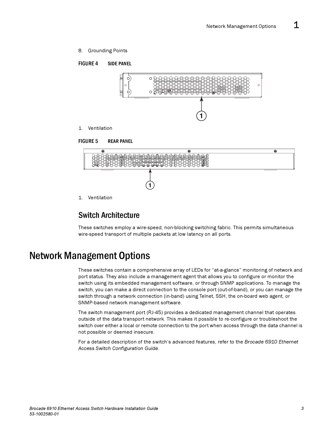
8. Grounding Points
1
1. Ventilation
1
1. Ventilation
Switch Architecture
These switches employ a wire-speed, non-blocking switching fabric. This permits simultaneous wire-speed transport of multiple packets at low latency on all ports.
Network Management Options
These switches contain a comprehensive array of LEDs for “at-a-glance” monitoring of network and port status. They also include a management agent that allows you to configure or monitor the switch using its embedded management software, or through SNMP applications. To manage the switch, you can make a direct connection to the console port (out-of-band), or you can manage the switch through a network connection (in-band) using Telnet, SSH, the on-board web agent, or SNMP-based network management software.
The switch management port (RJ-45) provides a dedicated management channel that operates outside of the data transport network. This makes it possible to re-configure or troubleshoot the switch over either a local or remote connection to the port when access through the data channel is not possible or deemed insecure.
For a detailed description of the switch’s advanced features, refer to the Brocade 6910 Ethernet Access Switch Configuration Guide.
Brocade 6910 Ethernet Access Switch Hardware Installation Guide | 3 |
53-1002580-01 | |