2 Connecting to a Power Source
4.The switch chassis is connected internaly to 0 V. This circuit is connected to the grounding terminal on the front of the switch. The surface area around this terminal is not painted in order to provide for a good connection. Attach a 18 AWG stranded copper wire to the grounding terminal on the switch.
5.Then attach the grounding wire to the ground point on the rack.
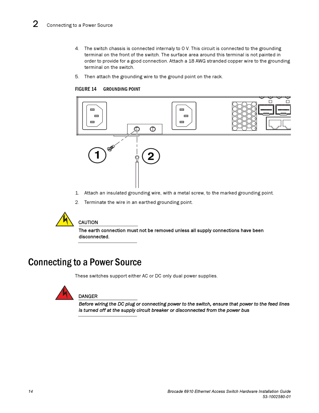
FIGURE 14 GROUNDING POINT
1![]() 2
2
1.Attach an insulated grounding wire, with a metal screw, to the marked grounding point.
2.Terminate the wire in an earthed grounding point.
CAUTION
The earth connection must not be removed unless all supply connections have been disconnected.
Connecting to a Power Source
These switches support either AC or DC only dual power supplies.
DANGER
Before wiring the DC plug or connecting power to the switch, ensure that power to the feed lines is turned off at the supply circuit breaker or disconnected from the power bus
14 | Brocade 6910 Ethernet Access Switch Hardware Installation Guide |
|
|