B Twisted-Pair Cable and Pin Assignments

TABLE 6

10/100BASE-TX MDI and MDI-X PORT PINOUTS


Pin

MDI Signal Name

MDI-X Signal Name


1

Transmit Data plus (TD+)

Receive Data plus (RD+)


2

Transmit Data minus (TD-)

Receive Data minus (RD-)


3

Receive Data plus (RD+)

Transmit Data plus (TD+)


6

Receive Data minus (RD-)

Transmit Data minus (TD-)


4,5,7,8

Not used

Not used


NOTE

The “+” and “-” signs represent the polarity of the wires that make up each wire pair.

Straight-Through Wiring

If the twisted-pair cable is to join two ports and only one of the ports has an internal crossover (MDI-X), the two pairs of wires must be straight-through. (When auto-negotiation is enabled for any RJ-45 port on this switch, you can use either straight-through or crossover cable to connect to any device type.)

You must connect all four wire pairs as shown in the following diagram to support Gigabit Ethernet.

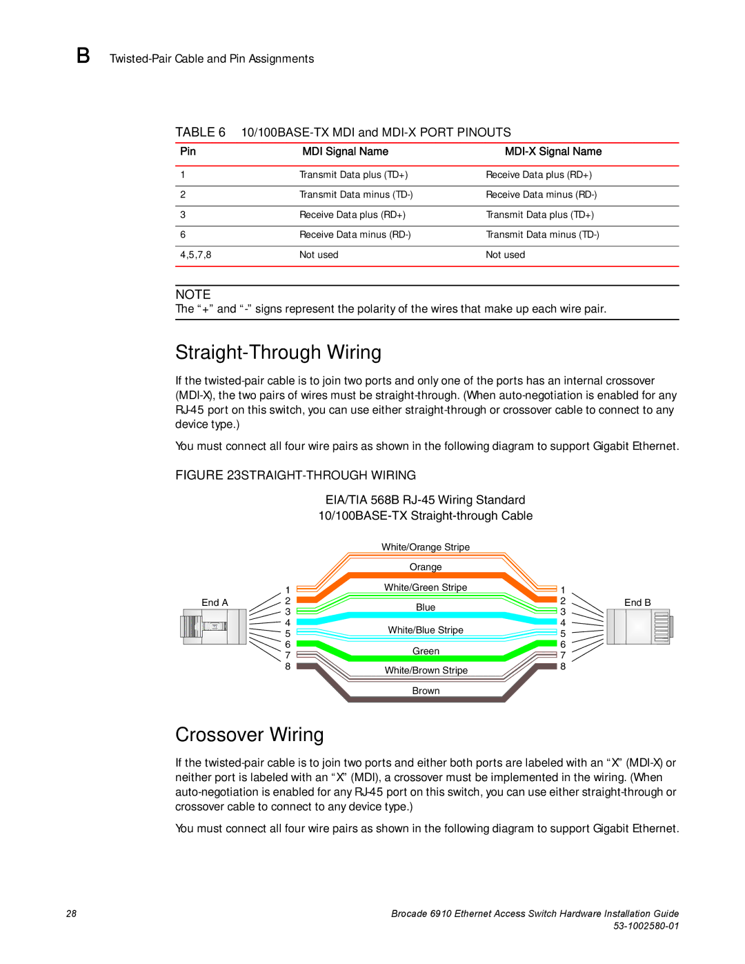
FIGURE 23 STRAIGHT-THROUGH WIRING

EIA/TIA 568B RJ-45 Wiring Standard 10/100BASE-TX Straight-through Cable

White/Orange Stripe


Orange


1

White/Green Stripe

1


End A

2

Blue

2

End B


3

3


4

White/Blue Stripe

4


5

5


6

Green

6


7

7


8

White/Brown Stripe

8


Brown

Crossover Wiring

If the twisted-pair cable is to join two ports and either both ports are labeled with an “X” (MDI-X) or neither port is labeled with an “X” (MDI), a crossover must be implemented in the wiring. (When auto-negotiation is enabled for any RJ-45 port on this switch, you can use either straight-through or crossover cable to connect to any device type.)

You must connect all four wire pairs as shown in the following diagram to support Gigabit Ethernet.

28

Brocade 6910 Ethernet Access Switch Hardware Installation Guide


53-1002580-01

Page 42
Image 42
Brocade Communications Systems 53-1002580-01 manual Straight-Through Wiring, Crossover Wiring