Connecting to the Alarm Port | 2 |
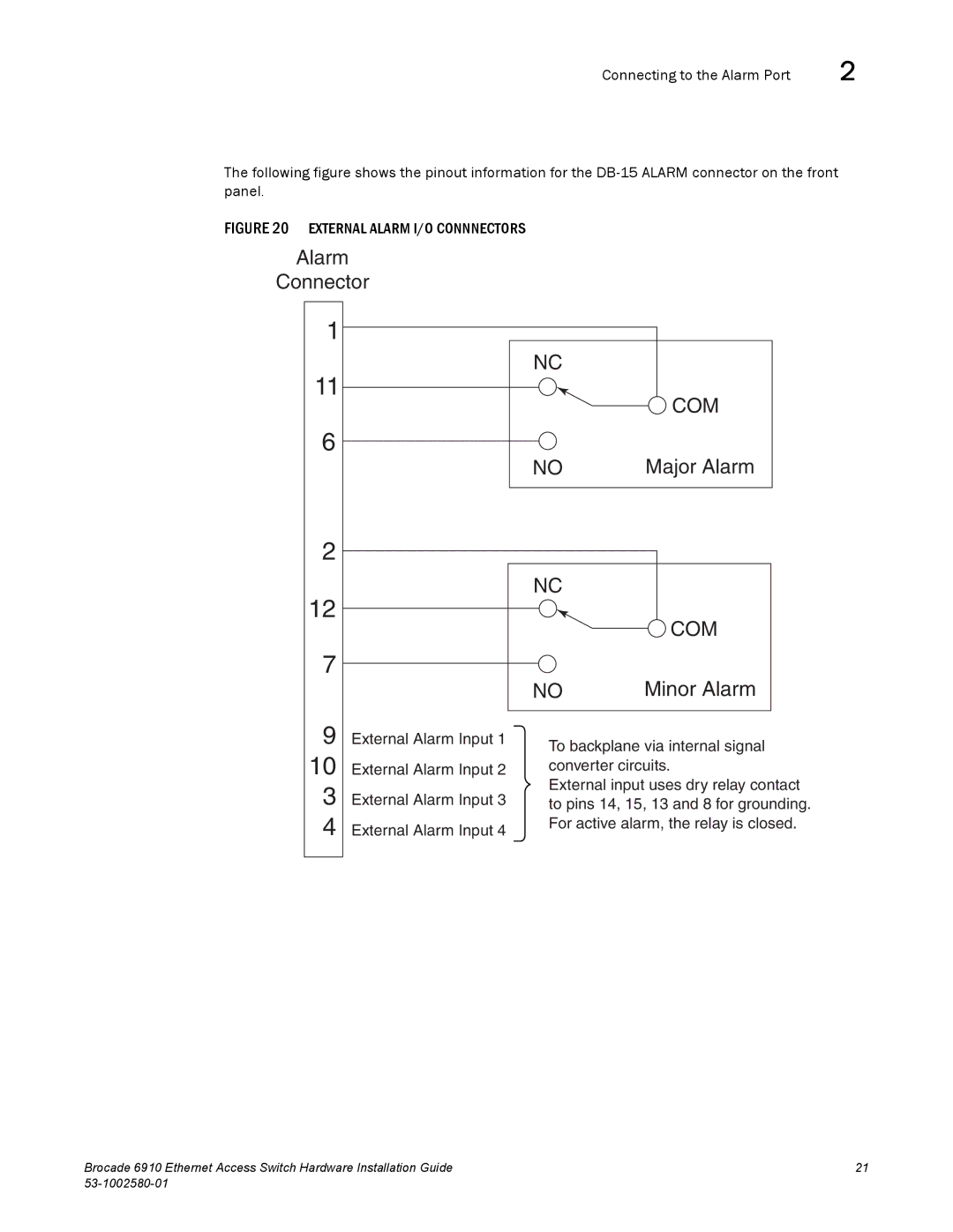
The following figure shows the pinout information for the
FIGURE 20 EXTERNAL ALARM I/O CONNNECTORS
Alarm
Connector
1
11
6
2
12
7
NC
![]() COM
COM
NO | Major Alarm |
NC
![]() COM
COM
9
10
3
4
External Alarm Input 1
External Alarm Input 2
External Alarm Input 3
External Alarm Input 4
NO | Minor Alarm |
To backplane via internal signal converter circuits.
External input uses dry relay contact to pins 14, 15, 13 and 8 for grounding. For active alarm, the relay is closed.
Brocade 6910 Ethernet Access Switch Hardware Installation Guide | 21 |
|
|