BAS-311E,311EL
Please read this manual before making any adjustments
SERVICE MANUAL
BAS-326E,326EL
DANGER
z Safety indications and their meanings
Symbols
Indications
Installation
x Notes on safety
Sewing
Cleaning
Maintenance and inspection
Finger guard, etc
c Warning labels
Safety devices Thread take-up cover Eye guard, Belt cover
Moving parts may cause injury
Explanation of models
INDEX
Chapter 4. Adjustments
Chapter 5. How to make up the work clamp
1. Needle bar, thread take-up, lower shaft and shuttle hook mechanism
Chapter 1. Mechanical description
Chapter 1. Mechanical description
2. Work clamp lifting mechanism 1 Solenoid type, 311E
e r q w t y u
w e q r
Work clamp lifting mechanism 2 311E, 311EL Pneumatictype
Work clamp lifting mechanism 326E
w eq r
e r w
3. Feed mechanism X axis 311E, 311EL, 326E, 326EL
u i y o
ey q
Feed mechanism Y axis 311E and 311EL
Feed mechanism Y axis 326E, 326EL
q w i r e t
4. Presser foot mechanism
r t e q w y u
Presser foot mechanism
e r q w
5. Thread trimmer mechanism
t yu i o
r r e q w
6. Thread nipper 1 when presser foot rises
Thread nipper 2 during thread trimming
q w e t y r
q w e r t
7. Thread wiper 1 vertical wiper standard
Thread wiper 2 horizontal wiper optional
q w e r
Chapter 2. Disassembly
Chapter 2. Disassembly
1. Covers 1 311E
q w r y e u t
q !1 e i y u o
Covers 2 311EL
Covers 3 326E, 326EL
w u o
2. Remove the bolt and the work clamp r
2. Feed mechanism
t y r q w
3. Remove the screw, the feed plate t and the needle sub plate y
3. Presser foot mechanism
w q u y e
e y r u w
4. Needle bar mechanism
t r o i
7 !6 y
r !7
5. Upper shaft mechanism
wt y ru o i e!0 q
5q !2 !1 6r !4
1. Loosen the set screw and remove the X-feed shaft q
6. Feed mechanism Y axis 1 311E and 311EL
w q e r t
2. Remove the screws and the work clamp arm w
Feed mechanism Y axis
q r t
Feed mechanism Y axis 3 326E, 326E
r w e q u q i t y
7. Feed mechanism X axis 1 311E
r y w e
u r q
Feed mechanism X axis 2 311EL and 326E, 326EL
@3 o 0!1 6 !2!3
@2 @0
w r q e
8. Lower shaft mechanism
1!0 o i
9. Work clamp lifter Solenoid type
i t q r
10. Thread nipper mechanism
r u r t y i e w q t r y o
@2 t
11. Thread trimmer mechanism
@0!3 !7
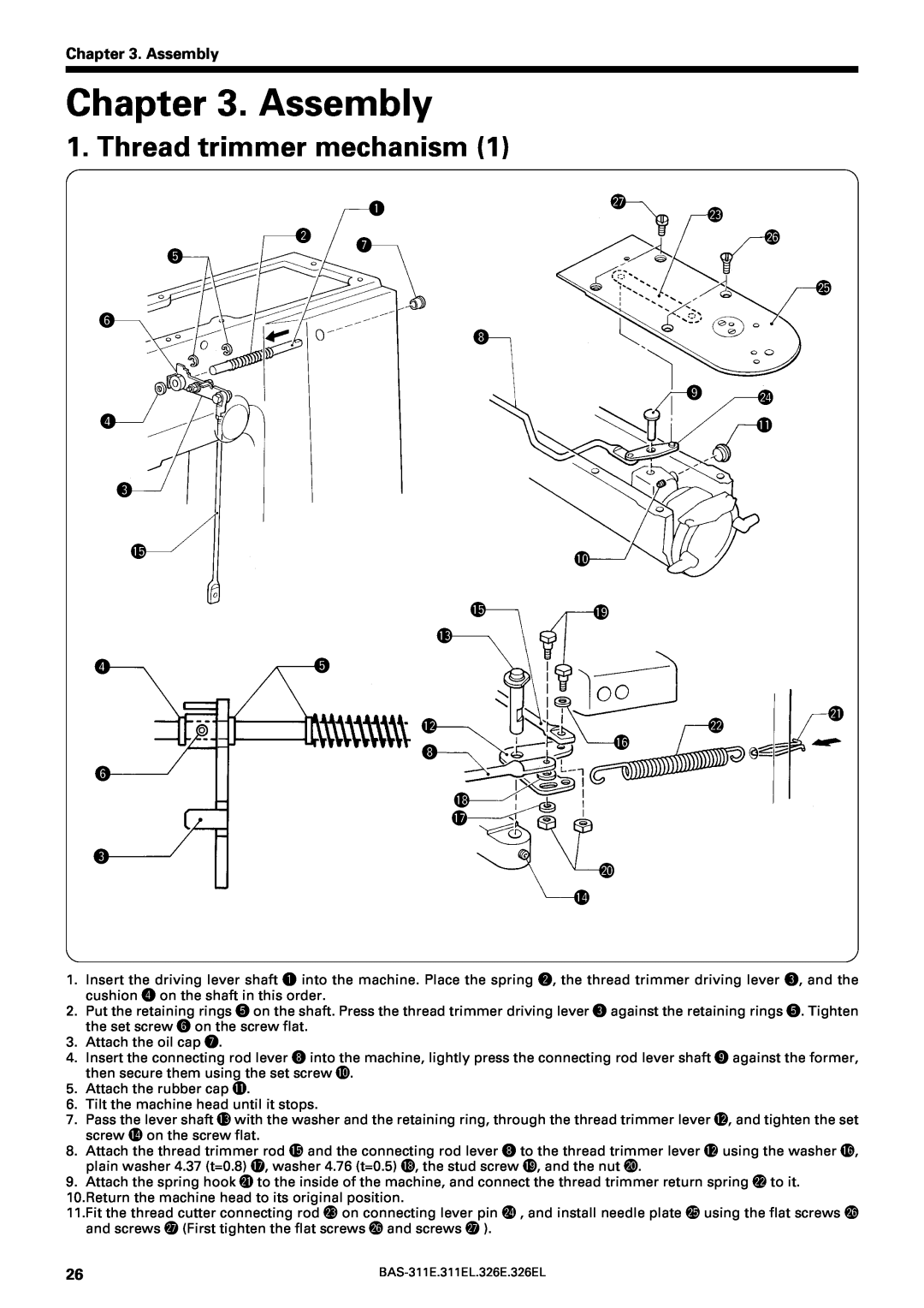
Chapter 3. Assembly
Chapter 3. Assembly
1. Thread trimmer mechanism
t y r e
2. Thread nipper mechanism
i 0 !1
work clamp lifter wire @1, and tighten the bolt @2
4 !5
o !1
3. Work clamp lifter mechanism
u @2 y @4 !4 t
e w q
u r y t e i u w q
Sliding portions of link shaft C q and link B w
e q w r
4. Feed mechanism X axis 311E
2 !3
Adjustment procedure
i u
Feed mechanism X axis 311EL, 326E
w !5
t 0i y
@0 w
Feed mechanism X axis 311EL and 326E
o @7
r !2
e 1!0
t r qty o
q 1w
#1 @4 @5
@9 #2 @8 #0 @3
@0 @2
@6 !6
Feed mechanism Y axis 326E
r q w e
5. Temporarily attach the work clamp Arm !2to the Y-feed bracket i using the bolts and washers
e q w t y r e q
6. Upper shaft mechanism
q w i
q !5
7. Needle bar mechanism
3!4 u i o
8. Presser foot mechanism
o 0 !4
w @1
q 1!4
@3 w
9. Lower shaft mechanism
w q e t o u 0y
10. Lower shaft Rotary hook
r r e o !0
t o e y i q u
i !0
r e t w q i u y !1 o
2. Secure the needle sub plate e with the screw r
12.Press the P key and adjust the X-sensor setting plate !7so that the needle !4is aligned with the home position X=0, Y=0 of the H-position standard plate !1
qt w
Feed guide mechanism Home position adjustment Y 311E and 311EL
Feed guide mechanism Home position adjustment Y 326E and 326EL
P key
o !0
13. Covers 311E
e q
@1 @0 @2
y w e i u t
311EL
326E · 326EL
o t !1
2. Adjusting the needle bar lift amount
Chapter 4. Adjustments
1. Adjusting the needle bar height adjustment
Chapter 4. Adjustments
5. Adjusting the shuttle race thread guide
3. Adjusting the needle clearance
4. Adjusting the driver needle guard
q w e
6. Adjusting the two-step work clamp lift amount
6-1. Solenoid type
yw w r
6-2. Pneumatic type
rr q
BAS-311E · 311EL
7. Adjusting the movable knife
7-1. Replacing the movable and fixed knives
u w q
A. After the movable knife and fixed knife are properly engaged, tighten shoulder screw
311E, 311EL
326E, 326EL
w o e y
8. Adjusting the lowest point of the presser foot
r q t
r e q w w
8-1. Presser foot adjustment
9. Changing the presser foot lift
q e
For horizontal wiper optional
10. Wiper adjustment
For vertical wiper standard
re y t q w
11. Adjusting the home position
X axis
Y axis 311E and 311EL
e r e r
Y axis 326E, 326EL
Adjusting the tension of Y-timing belt
12. Adjusting the tension of the timing belt
Adjusting the tension of X-timing belt 311E
e w r
Adjusting the tension of X-timing belt A326
311EL and 326E, 326EL
Adjusting the tension of X-timing belt B326
Lower shaft
13. Adjusting backlashes
Y-axis feed
15. Adjusting the thread trimmer driving lever position
14. Adjusting the driving lever stopper position
Most 0.15 mm
q q w
17. Adjusting the presser foot height
16. Work clamp lift components for manual operation Sole- noid type
y t r
18. Adjusting the needle up stop position
wu y
How to make up the work clamp
Chapter 5. How to make up the work clamp
1. How to make up clamping type work clamp
How to make up the feed plate
2. How to make up cassette type work clamp
How to make up the plastic work clamp
Cassette presser
Clamp spring
2. Components inside the control box
Chapter 6 Power supply and electrical parts adjustment
1. Precautions at the time of adjustment
Power supply circuit board
3. Fuse explanation
4. Connectors
Connector positions Outside of the control box
Outside of the panel Panel circuit board
Programmer and programmer circuit board
LCD contrast VR
1. Feed mechanism
Contact failure
2. Work clamp lifter and thread trimmer mechanisms
3. Sewing operation
Power
Power switch
supply circuit
5. Others
4. Programmer operation
DC fan
Emergency stop switch is rejected
Error E.12 appears
Error E.40 appears
Panel DIP switch functions
5. DIP switches
DIP switch A
DIP switch B
DIP switches inside the control box
DIP switch C
DIP switch D
メニュー
6. Changing special functions using the memory switches
BAS-300E series
MENU
Memory Switches 00 - 0F
Memory Switches 20 - 2F
Memory Switches 10 - 1F
Chapter 6 Power supply and electrical parts adjustment
BAS-300E series
7. Checking the input sensor and DIP switch input
OFF OFF
X-SCALE
9. Clearing all memory settings
8. Checking the input voltage
R / W
BAS-300E series
10. Confirming software version
Version number indication example
Program NO display
11. Error codes
Error codes E.9 * - E.F
Explanation of shapes
Chapter 7. Trouble shooting
Flowchart
Chapter
off?
work clamp
Chapter
Is the TEST
Chapter
Does the
needle at the upper position when NO
stops?
machine stop with the
Precautions
Problem solution and measures
Before adjustment
For 100 V, 110 V
For 200 V, 220 V, and
V, 380 V, 400 V, and
Chapter
Chapter
pressed
switches
#1.2
After a few
Presser
Chapter
Chapter
switch is
occurs
cannot sew
Chapter
S51038326LB-001
Chapter 8. 1. Gauge parts list according to subclasses
S51037326LA-001
Presser foot
Chapter 9. Gauge parts list
Chapter 9. Gauge parts list
Needle hole plate
Work clamp, Feed plate BAS-311E
OPTION PARTS
Feed plate blank and Work clamp blank BAS-311E
Work clamp and Feed plate BAS-311EL
Feed plate blank and Work clamp blank BAS-311EL
Feed mechanism BAS-326E
Feed mechanism Option parts BAS-326E
Feed mechanism BAS-326E, 326EL
For one-touch work clamp plate assy
Feed mechanism Option parts
Feed mechanism Option parts BAS-326E,326EL
BAS-311E.311EL.326E.326EL
Programmer assy Inner clamp device One-touch clamping device
Chapter 10. Option parts
Chapter 10. Option parts
Milling device WP stitch device Auto bobbin changer
Programmer
Inner clamping device Option device
For Supplry parts
Inner clamping device Option device BAS-326EL
A45254000
S20822101
For change the feed plate setting position
One-touch work clamp
S20289101
One-touch work clamp Option parts BAS-326EL
M-520K
Snap fastener and hook attachment device
M-508K
M-525K
For sewing the belt with hook
S24621-101
S24628-101
S18598-001
S18606-001
Wide perfect device
Needle cooler set
Soft work clamp set
Play prevention work clamp
For Horizontal Wiper
Thread wiper set Pneumatic type
2-step tension device
Auxiliary device
Chapter 10. Option parts
Yellow
Control Block Diagram
Presser toot
Brown
per shaft mo
Orange
Convertion
151-V11, V12
SERVICE MANUAL
Printed in Japan
I9080764 1999. 08. B