Connecting to the Network
 Redundant
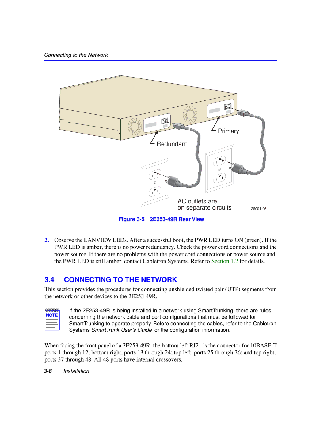
Primary
AC outlets are |
|
on separate circuits |
Figure 3-5 2E253-49R Rear View
2.Observe the LANVIEW LEDs. After a successful boot, the PWR LED turns ON (green). If the PWR LED is amber, there is no power redundancy. Check the power cord connections and the power source. If there are no problems with the power cord connections or power source and the PWR LED is still amber, contact Cabletron Systems. Refer to Section 1.2 for details.
3.4CONNECTING TO THE NETWORK
This section provides the procedures for connecting unshielded twisted pair (UTP) segments from the network or other devices to the
NOTE |
If the
When facing the front panel of a