SIMM Upgrade
B.4.2 Installing the DRAM SIMM
!
Observe all antistatic precautions when handling sensitive electronic equipment.
CAUTION
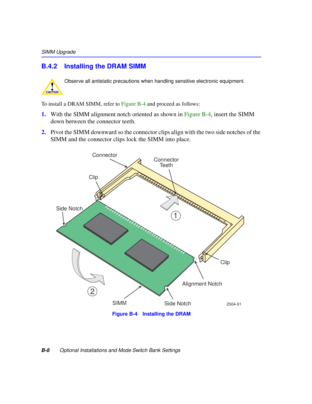
To install a DRAM SIMM, refer to Figure
1.With the SIMM alignment notch oriented as shown in Figure
2.Pivot the SIMM downward so the connector clips align with the two side notches of the SIMM and the connector clips lock the SIMM into place.
Connector
Connector
Teeth
Clip
Side Notch
1
Clip
Alignment Notch
2
SIMM | Side Notch |