SIMM Upgrade
B.4.1 Locating SIMMs
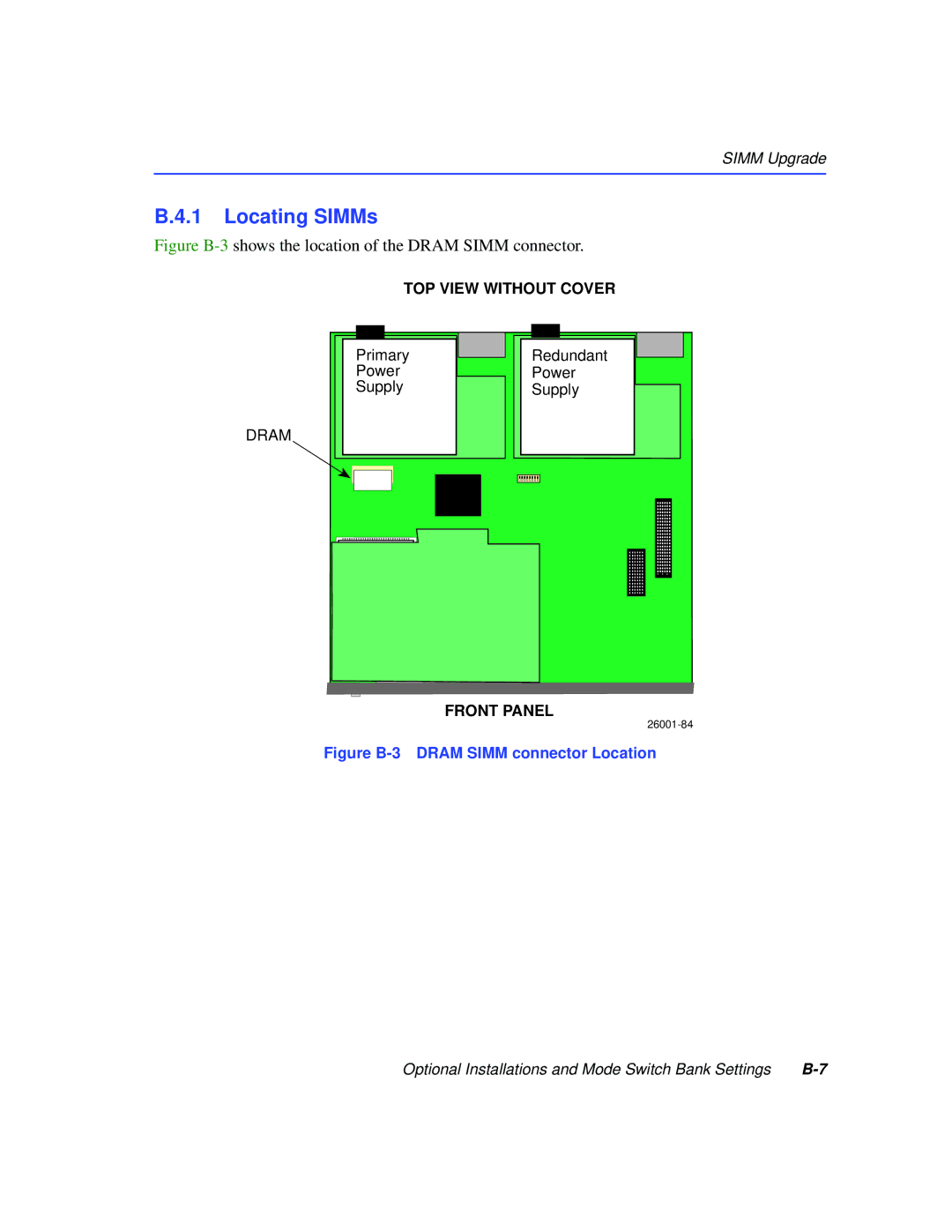
Figure B-3 shows the location of the DRAM SIMM connector.
TOP VIEW WITHOUT COVER
Primary
Power
Supply
Redundant
Power
Supply
DRAM
FRONT PANEL
Figure B-3 DRAM SIMM connector Location
Optional Installations and Mode Switch Bank Settings |