Setting the Mode Switches
B.3 SETTING THE MODE SWITCHES
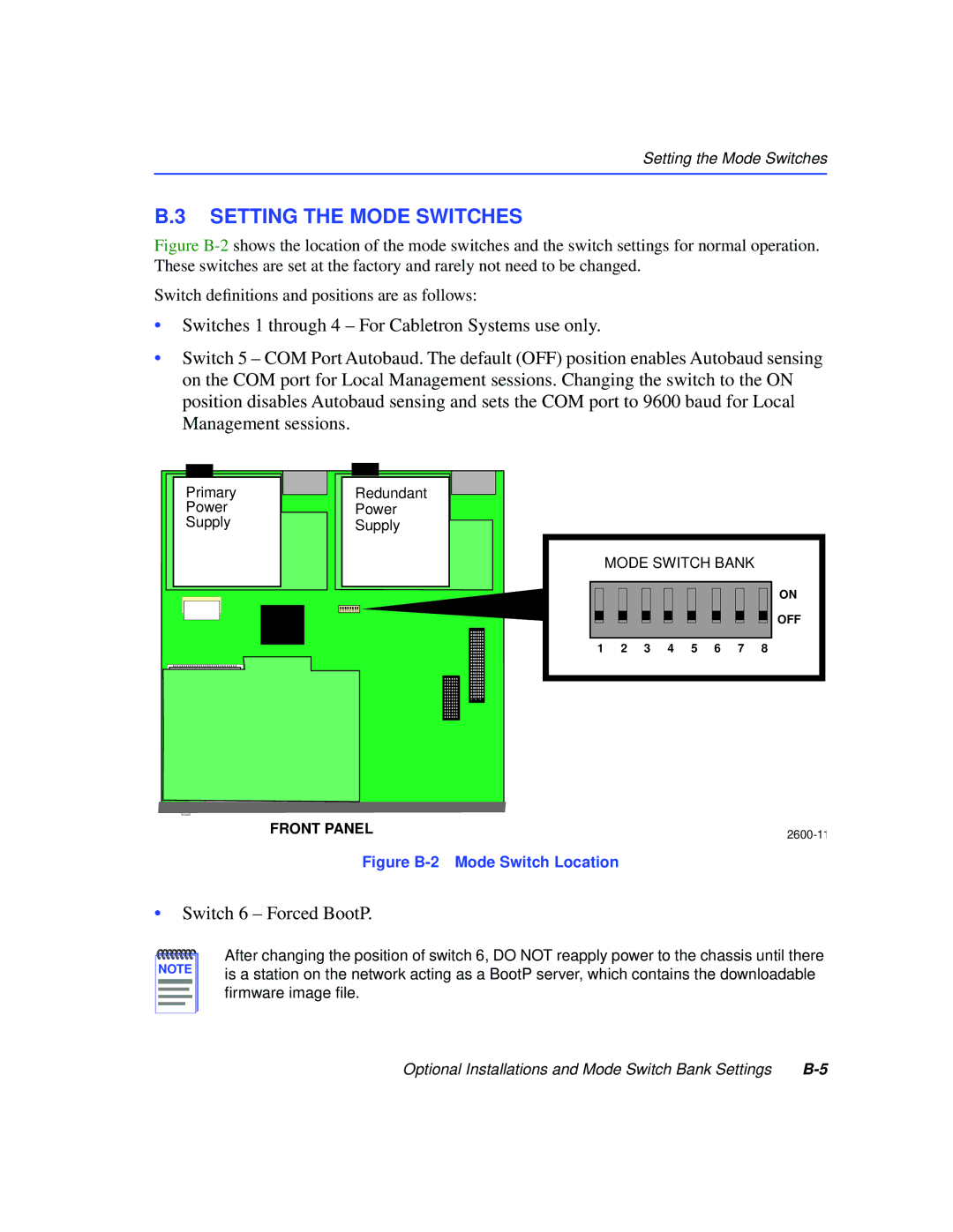
Figure B-2 shows the location of the mode switches and the switch settings for normal operation. These switches are set at the factory and rarely not need to be changed.
Switch definitions and positions are as follows:
•Switches 1 through 4 – For Cabletron Systems use only.
•Switch 5 – COM Port Autobaud. The default (OFF) position enables Autobaud sensing on the COM port for Local Management sessions. Changing the switch to the ON position disables Autobaud sensing and sets the COM port to 9600 baud for Local Management sessions.
Primary
Power
Supply
Redundant
Power
Supply
MODE SWITCH BANK
ON
OFF
1 2 3 4 5 6 7 8
FRONT PANEL | |
|
Figure B-2 Mode Switch Location
•Switch 6 – Forced BootP.
NOTE |
After changing the position of switch 6, DO NOT reapply power to the chassis until there is a station on the network acting as a BootP server, which contains the downloadable firmware image file.
Optional Installations and Mode Switch Bank Settings |