Table 3 — Thermistor Resistance vs Temperature
Values for Space Temperature Sensor, Supply Air Temperature Sensor, and
Outdoor Air Temperature Sensor
TEMP | TEMP | RESISTANCE |
(C) | (F) | (Ohms) |
335,651 | ||
242,195 | ||
176,683 | ||
130,243 | ||
96,974 | ||
5 | 72,895 | |
14 | 55,298 | |
23 | 42,315 | |
0 | 32 | 32,651 |
5 | 41 | 25,395 |
10 | 50 | 19,903 |
15 | 59 | 15,714 |
20 | 68 | 12,494 |
25 | 77 | 10,000 |
30 | 86 | 8,056 |
35 | 95 | 6,530 |
40 | 104 | 5,325 |
45 | 113 | 4,367 |
50 | 122 | 3,601 |
55 | 131 | 2,985 |
60 | 140 | 2,487 |
65 | 149 | 2,082 |
70 | 158 | 1,752 |
1 | 2 | 3 | 4 | 5 | 6 | RED(+) |
|
|
|
|
|
|
|
| |
|
|
|
|
| WHT(GND) | CCN COM | |
|
|
|
|
|
| ||
|
|
|
|
|
|
| |
|
|
| SEN |
|
|
|
|
| SW1 |
|
|
|
|
|
|
|
|
|
|
| BRN (GND) | SENSOR WIRING | |
|
|
|
|
| BLU (SPT) |
| |
Fig. 3 — Space Temperature Sensor
Typical Wiring (33ZCT55SPT)
1 | 2 | 3 | 4 | 5 | 6 | RED(+) |
|
|
|
|
|
|
|
| |
|
|
|
|
| WHT(GND) | CCN COM | |
|
|
|
|
|
| ||
|
|
|
|
|
|
| |
|
|
| SEN |
| SET |
|
|
| SW1 |
|
|
|
| BLK |
|
|
|
|
|
|
|
| |
|
|
|
|
|
| (T56) |
|
|
|
|
|
| BRN (GND) | SENSOR WIRING | |
|
|
|
|
| BLU (SPT) |
| |
|
|
|
|
|
|
| JUMPER |
|
|
|
|
|
|
| TERMINALS |
|
|
|
|
|
|
| AS SHOWN |
Cool Warm
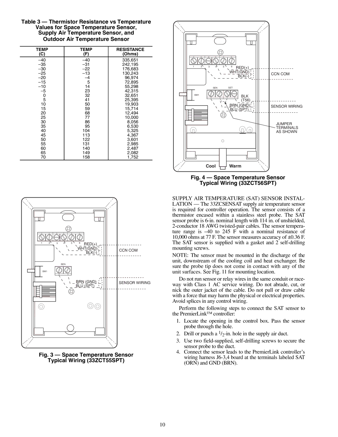
Fig. 4 — Space Temperature Sensor
Typical Wiring (33ZCT56SPT)
SUPPLY AIR TEMPERATURE (SAT) SENSOR INSTAL- LATION — The 33ZCSENSAT supply air temperature sensor is required for controller operation. The sensor consists of a thermistor encased within a stainless steel probe. The SAT sensor probe is
NOTE: The sensor must be mounted in the discharge of the unit, downstream of the cooling coil and heat exchanger. Be sure the probe tip does not come in contact with any of the unit surfaces. See Fig. 11 for mounting location.
Do not run sensor or relay wires in the same conduit or race- way with Class 1 AC service wiring. Do not abrade, cut, or nick the outer jacket of the cable. Do not pull or draw cable with a force that may harm the physical or electrical properties. Avoid splices in any control wiring.
Perform the following steps to connect the SAT sensor to the PremierLink™ controller:
1.Locate the opening in the control box. Pass the sensor probe through the hole.
2.Drill or punch a
3.Use two
4.Connect the sensor leads to the PremierLink controller’s wiring harness
10