PremierLink Connections
40RM Connections |
38AK, AKS, ARZ, ARS
Terminal
RED ![]()
RED
PWR
RED
HS3/EXH/RVS
ORN
HS2
PNK
HS1
WHT
R |
|
|
|
| |
Y1 | 40RM, 40RMQ, 40RMS | ||||
Y2 |
| HEAT ACCESSORY | |||
|
|
|
| ||
W1 |
|
| W1 |
| |
W2 |
|
| W2 |
| |
G | WHT C1 IFC C2 |
| C |
| |
|
| WHT |
|
|
|
C |
|
|
| ||
|
|
| |||
Board (TB)
R
Y1
Y2
CUT |
RELAYS
RED ![]()
![]()
RED
CMP2
CMP1
BLU
YEL
X |
CCR |
LLSV
W1
W2
G
CUT TO ISOLATE CONTROLLER POWER |
PWR J1 J8
FAN
GRN
BRN
CCSV
C
X
LEGEND
CCR
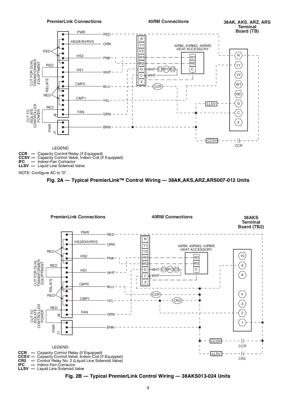
CCR — Capacity Control Relay (If Equipped)
CCSV — Capacity Control Valve, Indoor Coil (If Equipped)
IFC —
LLSV — Liquid Line Solenoid Valve
NOTE: Configure AC to “0”.
Fig. 2A — Typical PremierLink™ Control Wiring — 38AK,AKS,ARZ,ARS007-012 Units
PremierLink Connections
40RM Connections |
38AKS
Terminal
Board (TB2)
RED ![]()
RED
PWR
RED ![]()
HS3/EXH/RVS
ORN
HS2
PNK
HS1
WHT
R |
|
|
Y1 | 40RM, 40RMQ, 40RMS | |
Y2 |
| HEAT ACCESSORY |
|
| |
W1 |
| W1 |
W2 |
| W2 |
G | WHT C1 IFC C2 | C |
C WHT |
10
9
8
CUT |
RELAYS
RED ![]()
![]()
RED
CMP2
CMP1
BLU
YEL
X |
CCR
CR2
4
3
CUT TO ISOLATE CONTROLLER POWER |
PWR J1 J8
FAN
GRN
BRN
CCSV
2
1
LEGEND
CCR — Capacity Control Relay (If Equipped)
CCSV — Capacity Control Valve, Indoor Coil (If Equipped) CR2 — Control Relay No. 2 (Liquid Line Solenoid Valve) IFC —
LLSV — Liquid Line Solenoid Valve
CCR
LLSV ![]()
![]()
![]() CR2
CR2
Fig. 2B — Typical PremierLink Control Wiring — 38AKS013-024 Units
4