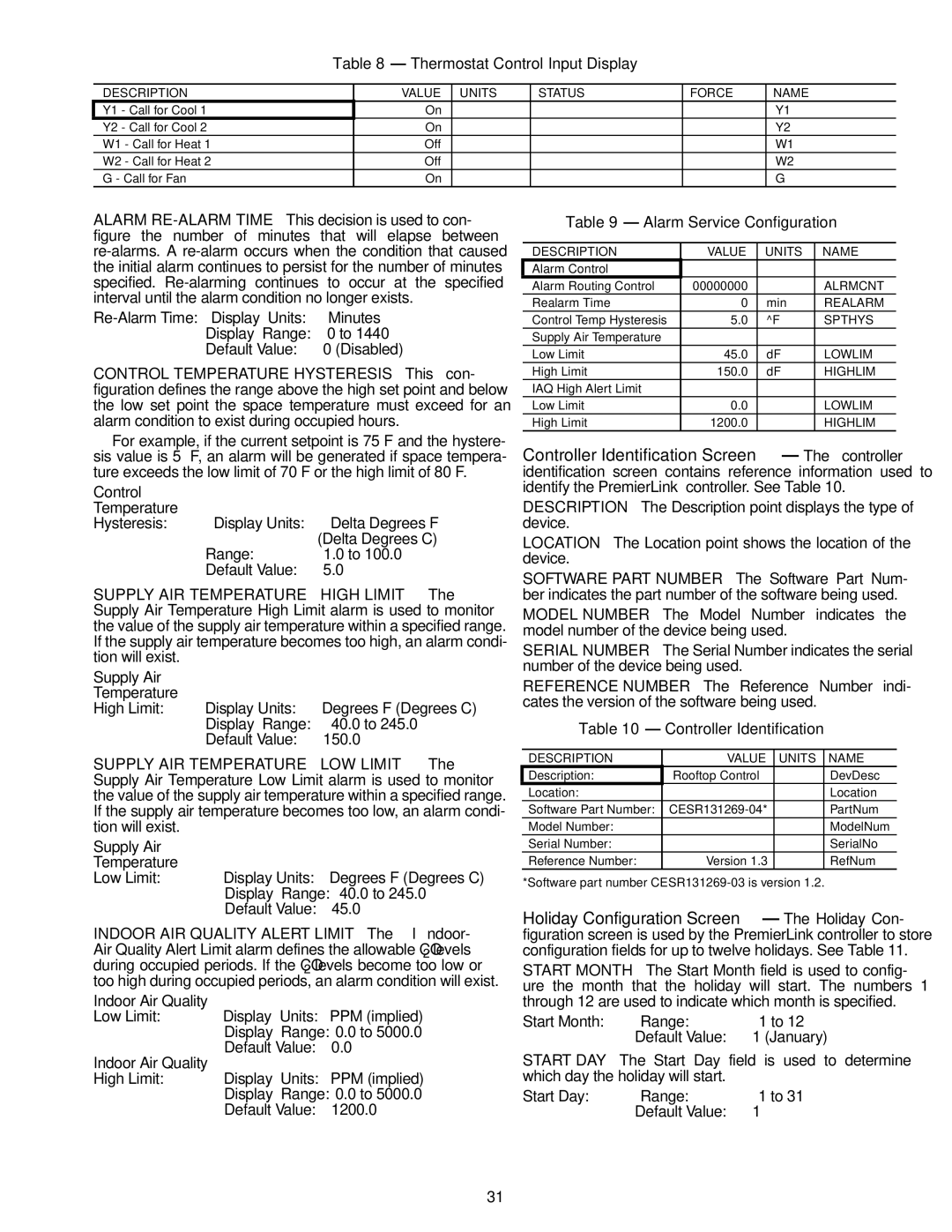
Table 8 — Thermostat Control Input Display
DESCRIPTION | VALUE | UNITS | STATUS | FORCE | NAME |
Y1 - Call for Cool 1 | On |
|
|
| Y1 |
Y2 - Call for Cool 2 | On |
|
|
| Y2 |
W1 - Call for Heat 1 | Off |
|
|
| W1 |
W2 - Call for Heat 2 | Off |
|
|
| W2 |
G - Call for Fan | On |
|
|
| G |
ALARM
Minutes | |
Display Range: | 0 to 1440 |
Default Value: | 0 (Disabled) |
CONTROL TEMPERATURE HYSTERESIS — This con- figuration defines the range above the high set point and below the low set point the space temperature must exceed for an alarm condition to exist during occupied hours.
Table 9 — Alarm Service Configuration
DESCRIPTION | VALUE | UNITS | NAME |
Alarm Control |
|
|
|
Alarm Routing Control | 00000000 |
| ALRMCNT |
Realarm Time | 0 | min | REALARM |
Control Temp Hysteresis | 5.0 | ^F | SPTHYS |
Supply Air Temperature |
|
|
|
Low Limit | 45.0 | dF | LOWLIM |
High Limit | 150.0 | dF | HIGHLIM |
IAQ High Alert Limit |
|
|
|
Low Limit | 0.0 |
| LOWLIM |
High Limit | 1200.0 |
| HIGHLIM |
For example, if the current setpoint is 75 F and the hystere- sis value is 5° F, an alarm will be generated if space tempera- ture exceeds the low limit of 70 F or the high limit of 80 F.
Control |
|
|
Temperature |
|
|
Hysteresis: | Display Units: | Delta Degrees F |
|
| (Delta Degrees C) |
| Range: | 1.0 to 100.0 |
| Default Value: | 5.0 |
SUPPLY AIR TEMPERATURE — HIGH LIMIT — The Supply Air Temperature High Limit alarm is used to monitor the value of the supply air temperature within a specified range. If the supply air temperature becomes too high, an alarm condi- tion will exist.
Supply Air
Temperature
High Limit: Display Units: Degrees F (Degrees C) Display Range:
SUPPLY AIR TEMPERATURE — LOW LIMIT — The Supply Air Temperature Low Limit alarm is used to monitor the value of the supply air temperature within a specified range. If the supply air temperature becomes too low, an alarm condi- tion will exist.
Supply Air
Temperature
Low Limit: Display Units: Degrees F (Degrees C) Display Range:
INDOOR AIR QUALITY ALERT LIMIT — The Indoor- Air Quality Alert Limit alarm defines the allowable CO2 levels during occupied periods. If the CO2 levels become too low or too high during occupied periods, an alarm condition will exist.
Indoor Air Quality
Low Limit: Display Units: PPM (implied) Display Range: 0.0 to 5000.0 Default Value: 0.0
Indoor Air Quality
High Limit: Display Units: PPM (implied) Display Range: 0.0 to 5000.0 Default Value: 1200.0
Controller Identification Screen — The controller identification screen contains reference information used to identify the PremierLink™ controller. See Table 10.
DESCRIPTION — The Description point displays the type of device.
LOCATION — The Location point shows the location of the device.
SOFTWARE PART NUMBER — The Software Part Num- ber indicates the part number of the software being used.
MODEL NUMBER — The Model Number indicates the model number of the device being used.
SERIAL NUMBER — The Serial Number indicates the serial number of the device being used.
REFERENCE NUMBER — The Reference Number indi- cates the version of the software being used.
Table 10 — Controller Identification
DESCRIPTION | VALUE | UNITS | NAME |
Description: | Rooftop Control |
| DevDesc |
Location: |
|
| Location |
Software Part Number: |
| PartNum | |
Model Number: |
|
| ModelNum |
Serial Number: |
|
| SerialNo |
Reference Number: | Version 1.3 |
| RefNum |
*Software part number
Holiday Configuration Screen — The Holiday Con- figuration screen is used by the PremierLink controller to store configuration fields for up to twelve holidays. See Table 11.
START MONTH — The Start Month field is used to config- ure the month that the holiday will start. The numbers 1 through 12 are used to indicate which month is specified.
Start Month: | Range: | 1 to 12 |
| Default Value: | 1 (January) |
START DAY — The Start Day field is used to determine which day the holiday will start.
Start Day: | Range: | 1 to 31 |
| Default Value: | 1 |
31