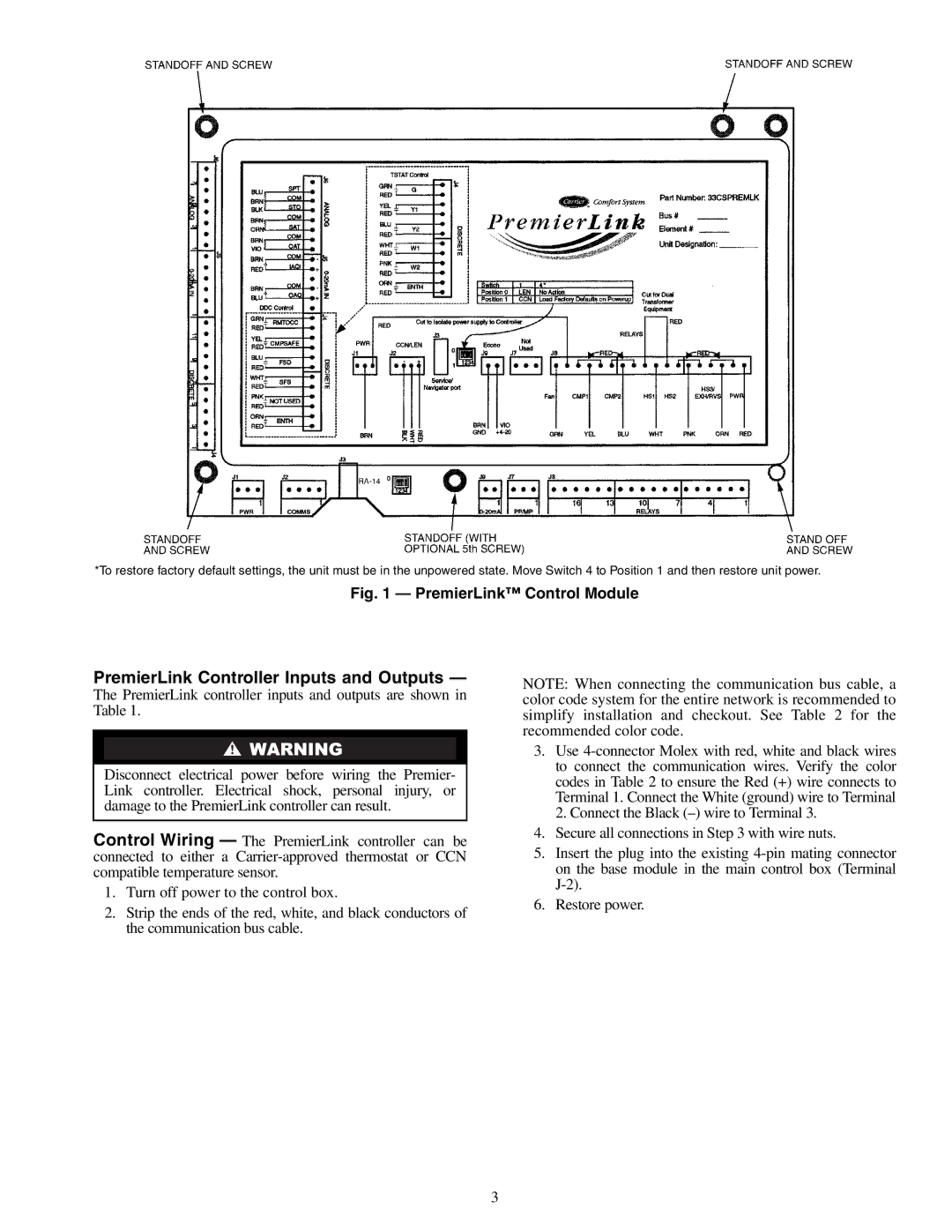
*To restore factory default settings, the unit must be in the unpowered state. Move Switch 4 to Position 1 and then restore unit power.
Fig. 1 — PremierLink™ Control Module
PremierLink Controller Inputs and Outputs —
The PremierLink controller inputs and outputs are shown in Table 1.
Disconnect electrical power before wiring the Premier- Link controller. Electrical shock, personal injury, or damage to the PremierLink controller can result.
Control Wiring — The PremierLink controller can be connected to either a
1.Turn off power to the control box.
2.Strip the ends of the red, white, and black conductors of the communication bus cable.
NOTE: When connecting the communication bus cable, a color code system for the entire network is recommended to simplify installation and checkout. See Table 2 for the recommended color code.
3.Use
4.Secure all connections in Step 3 with wire nuts.
5.Insert the plug into the existing
6.Restore power.
3