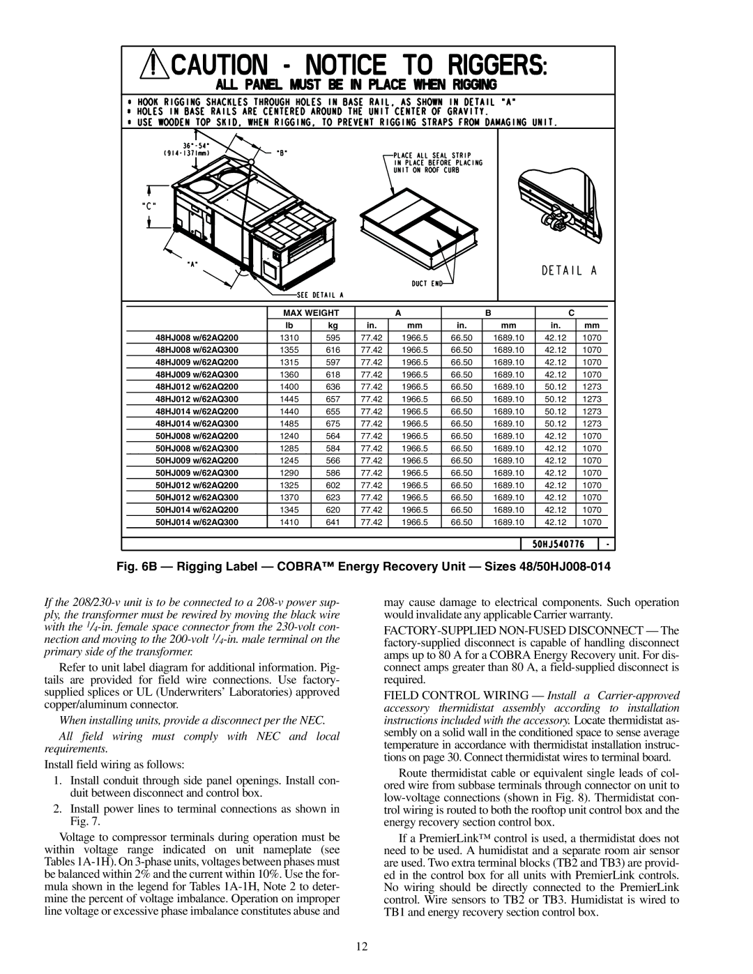
| MAX WEIGHT |
| A |
| B |
| C | |
| lb | kg | in. | mm | in. | mm | in. | mm |
48HJ008 w/62AQ200 | 1310 | 595 | 77.42 | 1966.5 | 66.50 | 1689.10 | 42.12 | 1070 |
48HJ008 w/62AQ300 | 1355 | 616 | 77.42 | 1966.5 | 66.50 | 1689.10 | 42.12 | 1070 |
48HJ009 w/62AQ200 | 1315 | 597 | 77.42 | 1966.5 | 66.50 | 1689.10 | 42.12 | 1070 |
48HJ009 w/62AQ300 | 1360 | 618 | 77.42 | 1966.5 | 66.50 | 1689.10 | 42.12 | 1070 |
48HJ012 w/62AQ200 | 1400 | 636 | 77.42 | 1966.5 | 66.50 | 1689.10 | 50.12 | 1273 |
48HJ012 w/62AQ300 | 1445 | 657 | 77.42 | 1966.5 | 66.50 | 1689.10 | 50.12 | 1273 |
48HJ014 w/62AQ200 | 1440 | 655 | 77.42 | 1966.5 | 66.50 | 1689.10 | 50.12 | 1273 |
48HJ014 w/62AQ300 | 1485 | 675 | 77.42 | 1966.5 | 66.50 | 1689.10 | 50.12 | 1273 |
50HJ008 w/62AQ200 | 1240 | 564 | 77.42 | 1966.5 | 66.50 | 1689.10 | 42.12 | 1070 |
50HJ008 w/62AQ300 | 1285 | 584 | 77.42 | 1966.5 | 66.50 | 1689.10 | 42.12 | 1070 |
50HJ009 w/62AQ200 | 1245 | 566 | 77.42 | 1966.5 | 66.50 | 1689.10 | 42.12 | 1070 |
50HJ009 w/62AQ300 | 1290 | 586 | 77.42 | 1966.5 | 66.50 | 1689.10 | 42.12 | 1070 |
50HJ012 w/62AQ200 | 1325 | 602 | 77.42 | 1966.5 | 66.50 | 1689.10 | 42.12 | 1070 |
50HJ012 w/62AQ300 | 1370 | 623 | 77.42 | 1966.5 | 66.50 | 1689.10 | 42.12 | 1070 |
50HJ014 w/62AQ200 | 1345 | 620 | 77.42 | 1966.5 | 66.50 | 1689.10 | 42.12 | 1070 |
50HJ014 w/62AQ300 | 1410 | 641 | 77.42 | 1966.5 | 66.50 | 1689.10 | 42.12 | 1070 |
Fig. 6B — Rigging Label — COBRA™ Energy Recovery Unit — Sizes 48/50HJ008-014
If the
Refer to unit label diagram for additional information. Pig- tails are provided for field wire connections. Use factory- supplied splices or UL (Underwriters’ Laboratories) approved copper/aluminum connector.
When installing units, provide a disconnect per the NEC.
All field wiring must comply with NEC and local requirements.
Install field wiring as follows:
1.Install conduit through side panel openings. Install con- duit between disconnect and control box.
2.Install power lines to terminal connections as shown in Fig. 7.
Voltage to compressor terminals during operation must be within voltage range indicated on unit nameplate (see Tables
may cause damage to electrical components. Such operation would invalidate any applicable Carrier warranty.
FIELD CONTROL WIRING — Install a
Route thermidistat cable or equivalent single leads of col- ored wire from subbase terminals through connector on unit to
If a PremierLink™ control is used, a thermidistat does not need to be used. A humidistat and a separate room air sensor are used. Two extra terminal blocks (TB2 and TB3) are provid- ed in the control box for all units with PremierLink controls. No wiring should be directly connected to the PremierLink control. Wire sensors to TB2 or TB3. Humidistat is wired to TB1 and energy recovery section control box.
12