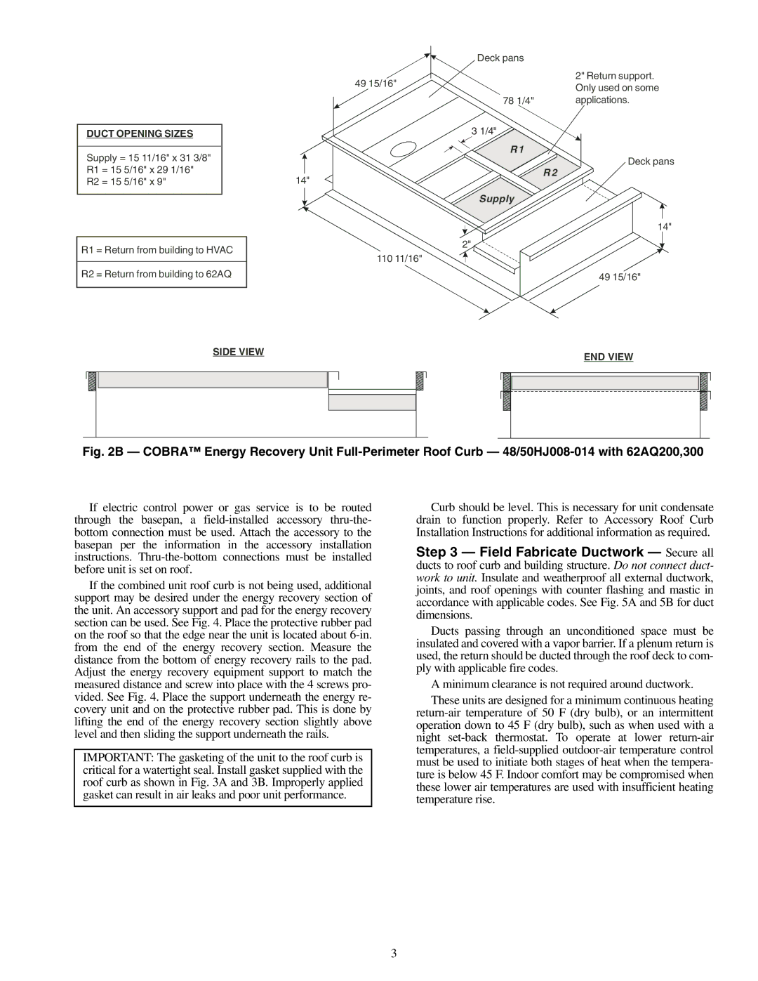
DUCT OPENING SIZES |
|
| ||
|
|
| ||
Supply = 15 11/16" x 31 3/8" |
|
| ||
|
| |||
R1 | = 15 | 5/16" x 29 1/16" |
|
|
R2 | = 15 | 5/16" x 9" | 14" | |
|
|
|
|
|
|
|
|
|
|
R1 = Return from building to HVAC
R2 = Return from building to 62AQ
SIDE VIEW
|
|
| Deck pans |
|
|
|
|
| 2" Return support. |
49 | 15/1 | 6" |
| |
| Only used on some | |||
|
|
|
| |
78 1/4" | applications. | |||
3 1/4![]()
![]()
R1
Deck pans
R 2
Supply
14"
2"
110 11/16"
49 15/16"
END VIEW
Fig. 2B — COBRA™ Energy Recovery Unit Full-Perimeter Roof Curb — 48/50HJ008-014 with 62AQ200,300
If electric control power or gas service is to be routed through the basepan, a
If the combined unit roof curb is not being used, additional support may be desired under the energy recovery section of the unit. An accessory support and pad for the energy recovery section can be used. See Fig. 4. Place the protective rubber pad on the roof so that the edge near the unit is located about
IMPORTANT: The gasketing of the unit to the roof curb is critical for a watertight seal. Install gasket supplied with the roof curb as shown in Fig. 3A and 3B. Improperly applied gasket can result in air leaks and poor unit performance.
Curb should be level. This is necessary for unit condensate drain to function properly. Refer to Accessory Roof Curb Installation Instructions for additional information as required.
Step 3 — Field Fabricate Ductwork — Secure all ducts to roof curb and building structure. Do not connect duct- work to unit. Insulate and weatherproof all external ductwork, joints, and roof openings with counter flashing and mastic in accordance with applicable codes. See Fig. 5A and 5B for duct dimensions.
Ducts passing through an unconditioned space must be insulated and covered with a vapor barrier. If a plenum return is used, the return should be ducted through the roof deck to com- ply with applicable fire codes.
A minimum clearance is not required around ductwork.
These units are designed for a minimum continuous heating
3