TROUBLESHOOTING
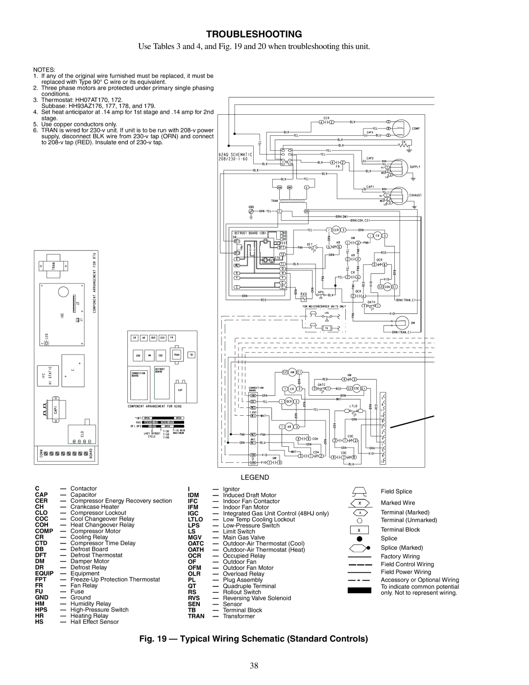
Use Tables 3 and 4, and Fig. 19 and 20 when troubleshooting this unit.
NOTES:
1.If any of the original wire furnished must be replaced, it must be replaced with Type 90° C wire or its equivalent.
2.Three phase motors are protected under primary single phasing conditions.
3.Thermostat: HH07AT170, 172.
Subbase: HH93AZ176, 177, 178, and 179.
4.Set heat anticipator at .14 amp for 1st stage and .14 amp for 2nd stage.
5.Use copper conductors only.
6. TRAN is wired for
C— Contactor CAP — Capacitor
CER — Compressor Energy Recovery section
CH — Crankcase Heater CLO — Compressor Lockout COC — Cool Changeover Relay COH — Heat Changeover Relay COMP — Compressor Motor
CR — Cooling Relay
CTD — Compressor Time Delay
DB — Defrost Board
DFT — Defrost Thermostat
DM — Damper Motor
DR — Defrost Relay EQUIP — Equipment
FPT —
FR — Fan Relay
FU — Fuse GND — Ground
HM — Humidity Relay
HPS —
HR — Heating Relay
HS — Hall Effect Sensor
LEGEND
I— Ignitor
IDM | — Induced Draft Motor |
IFC | — Indoor Fan Contactor |
IFM | — Indoor Fan Motor |
IGC | — Integrated Gas Unit Control (48HJ only) |
LTLO | — Low Temp Cooling Lockout |
LPS | — |
LS | — Limit Switch |
MGV | — Main Gas Valve |
OATC | — |
OATH | — |
OCR | — Occupied Relay |
OF | — Outdoor Fan |
OFM | — Outdoor Fan Motor |
OLR | — Overload Relay |
PL | — Plug Assembly |
QT | — Quadruple Terminal |
RS | — Rollout Switch |
RVS | — Reversing Valve Solenoid |
SEN | — Sensor |
TB | — Terminal Block |
TRAN | — Transformer |
Field Splice
Marked Wire
Terminal (Marked)
Terminal (Unmarked)
Terminal Block
Splice
Splice (Marked)
Factory Wiring Field Control Wiring Field Power Wiring Accessory or Optional Wiring To indicate common potential only. Not to represent wiring.
Fig. 19 — Typical Wiring Schematic (Standard Controls)
38