| UNIT SIZE | EQUIPMENT SUPPORT | DIMENSIONS (in.) |
| |||||
4” | PART NUMBER | A | B | C |
| ||||
|
| ||||||||
CRAQSUPT001A00 | 36.9 | 40 | 8 to 14 |
| |||||
| |||||||||
A | CRAQSUPT002A00 | 36.9 | 40 | 14 to 24 |
| ||||
|
| ||||||||
|
| CRAQSUPT003A00 | 49.7 | 54 | 8 to 14 |
| |||
| Ton | ||||||||
CRAQSUPT004A00 | 49.7 | 54 | 14 to 24 | ||||||
|
|
| |||||||
|
|
|
|
|
|
|
|
| |
|
| ENERGY | HVAC UNIT |
|
| RECOVERY |
|
C” |
| SECTION |
|
|
|
| |
| SCREW |
|
|
| SUPPORT |
|
|
| IN PLACE | PAD |
|
| ADJUSTABLE | CURB | |
|
| ||
| EQUIPMENT |
| |
| ROOF |
| |
| SUPPORT |
| |
|
|
|
10” x B (SEE CHART) PROTECTIVE RUBBER PAD (EPDM)
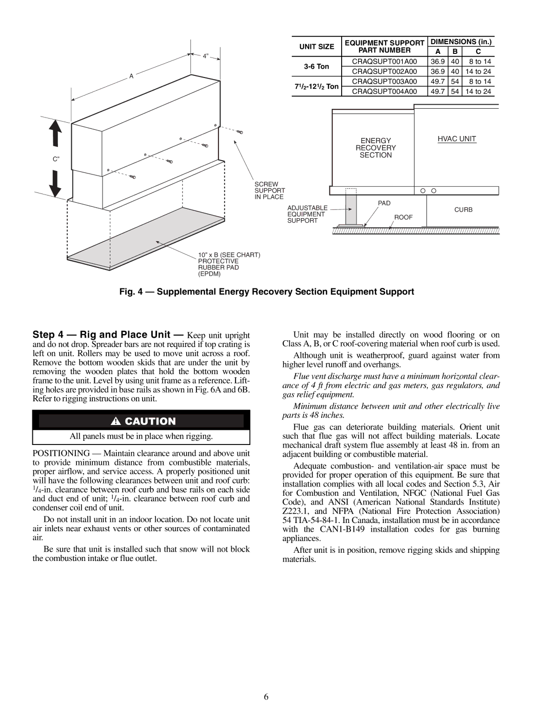
Fig. 4 — Supplemental Energy Recovery Section Equipment Support
Step 4 — Rig and Place Unit — Keep unit upright and do not drop. Spreader bars are not required if top crating is left on unit. Rollers may be used to move unit across a roof. Remove the bottom wooden skids that are under the unit by removing the wooden plates that hold the bottom wooden frame to the unit. Level by using unit frame as a reference. Lift- ing holes are provided in base rails as shown in Fig. 6A and 6B. Refer to rigging instructions on unit.
All panels must be in place when rigging.
POSITIONING — Maintain clearance around and above unit to provide minimum distance from combustible materials, proper airflow, and service access. A properly positioned unit will have the following clearances between unit and roof curb:
Do not install unit in an indoor location. Do not locate unit air inlets near exhaust vents or other sources of contaminated air.
Be sure that unit is installed such that snow will not block the combustion intake or flue outlet.
Unit may be installed directly on wood flooring or on Class A, B, or C
Although unit is weatherproof, guard against water from higher level runoff and overhangs.
Flue vent discharge must have a minimum horizontal clear- ance of 4 ft from electric and gas meters, gas regulators, and gas relief equipment.
Minimum distance between unit and other electrically live parts is 48 inches.
Flue gas can deteriorate building materials. Orient unit such that flue gas will not affect building materials. Locate mechanical draft system flue assembly at least 48 in. from an adjacent building or combustible material.
Adequate combustion- and
After unit is in position, remove rigging skids and shipping materials.
6
