NOTE: For wire runs up 50 ft, use no. 18 AWG (American Wire Gage) insulated wire (35 C minimum). For 50 to 75 ft, use no. 16 AWG insulated wire (35 C minimum). For over 75 ft, use no. 14 AWG insulated wire (35 C minimum). All wire larger than no. 18 AWG cannot be directly connected to the thermostat and will require a junction box and splice at the thermostat.
Pass the control wires through the hole provided in the cor- ner post; then feed wires through the raceway built into the corner post to the
control box. See Fig. 10. The raceway provides the UL required clearance between high- and
NOTE: A humidistat and a temperature sensor can be used in place of a thermidistat for PremierLink™ units.
HEAT ANTICIPATOR SETTINGS — Set heat anticipator settings at .14 amp for the first stage and .14 amp for second- stage heating, when available.
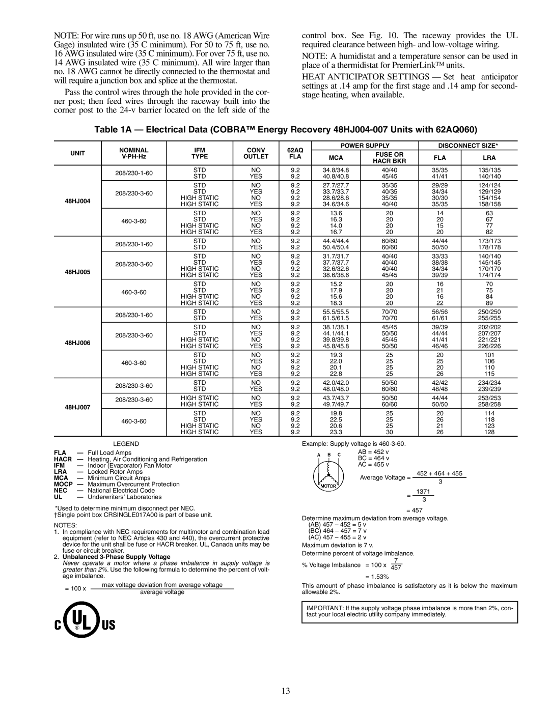
Table 1A — Electrical Data (COBRA™ Energy Recovery
| NOMINAL | IFM | CONV | 62AQ | POWER SUPPLY | DISCONNECT SIZE* | ||
UNIT | TYPE | OUTLET | FLA | MCA | FUSE OR | FLA | LRA | |
| HACR BKR | |||||||
|
|
|
|
|
|
|
| |
| STD | NO | 9.2 | 34.8/34.8 | 40/40 | 35/35 | 135/135 | |
| STD | YES | 9.2 | 40.8/40.8 | 45/45 | 41/41 | 140/140 | |
|
| |||||||
|
| STD | NO | 9.2 | 27.7/27.7 | 35/35 | 29/29 | 124/124 |
| STD | YES | 9.2 | 33.7/33.7 | 40/35 | 34/34 | 129/129 | |
| HIGH STATIC | NO | 9.2 | 28.6/28.6 | 35/35 | 30/30 | 154/154 | |
48HJ004 |
| |||||||
| HIGH STATIC | YES | 9.2 | 34.6/34.6 | 40/40 | 35/35 | 158/158 | |
|
| |||||||
|
| STD | NO | 9.2 | 13.6 | 20 | 14 | 63 |
| STD | YES | 9.2 | 16.3 | 20 | 20 | 67 | |
|
| HIGH STATIC | NO | 9.2 | 14.0 | 20 | 15 | 77 |
|
| HIGH STATIC | YES | 9.2 | 16.7 | 20 | 20 | 82 |
| STD | NO | 9.2 | 44.4/44.4 | 60/60 | 44/44 | 173/173 | |
| STD | YES | 9.2 | 50.4/50.4 | 60/60 | 50/50 | 178/178 | |
|
| |||||||
|
| STD | NO | 9.2 | 31.7/31.7 | 40/40 | 33/33 | 140/140 |
| STD | YES | 9.2 | 37.7/37.7 | 40/40 | 38/38 | 145/145 | |
48HJ005 |
| HIGH STATIC | NO | 9.2 | 32.6/32.6 | 40/40 | 34/34 | 170/170 |
| HIGH STATIC | YES | 9.2 | 38.6/38.6 | 45/45 | 39/39 | 174/174 | |
|
| |||||||
|
| STD | NO | 9.2 | 15.2 | 20 | 16 | 70 |
| STD | YES | 9.2 | 17.9 | 20 | 21 | 75 | |
| HIGH STATIC | NO | 9.2 | 15.6 | 20 | 16 | 84 | |
|
| |||||||
|
| HIGH STATIC | YES | 9.2 | 18.3 | 20 | 22 | 89 |
| STD | NO | 9.2 | 55.5/55.5 | 70/70 | 56/56 | 250/250 | |
| STD | YES | 9.2 | 61.5/61.5 | 70/70 | 61/61 | 255/255 | |
|
| |||||||
|
| STD | NO | 9.2 | 38.1/38.1 | 45/45 | 39/39 | 202/202 |
| STD | YES | 9.2 | 44.1/44.1 | 50/50 | 44/44 | 207/207 | |
| HIGH STATIC | NO | 9.2 | 39.8/39.8 | 45/45 | 41/41 | 221/221 | |
48HJ006 |
| |||||||
| HIGH STATIC | YES | 9.2 | 45.8/45.8 | 50/50 | 46/46 | 226/226 | |
|
| |||||||
|
| STD | NO | 9.2 | 19.3 | 25 | 20 | 101 |
| STD | YES | 9.2 | 22.0 | 25 | 25 | 106 | |
| HIGH STATIC | NO | 9.2 | 20.1 | 25 | 20 | 110 | |
|
| |||||||
|
| HIGH STATIC | YES | 9.2 | 22.8 | 25 | 26 | 115 |
| STD | NO | 9.2 | 42.0/42.0 | 50/50 | 42/42 | 234/234 | |
| STD | YES | 9.2 | 48.0/48.0 | 60/60 | 48/48 | 239/239 | |
|
| |||||||
| HIGH STATIC | NO | 9.2 | 43.7/43.7 | 50/50 | 44/44 | 253/253 | |
| HIGH STATIC | YES | 9.2 | 49.7/49.7 | 60/60 | 50/50 | 258/258 | |
48HJ007 |
| |||||||
| STD | NO | 9.2 | 19.8 | 25 | 20 | 114 | |
|
| |||||||
| STD | YES | 9.2 | 22.5 | 25 | 26 | 118 | |
| HIGH STATIC | NO | 9.2 | 20.6 | 25 | 21 | 123 | |
|
| |||||||
|
| HIGH STATIC | YES | 9.2 | 23.3 | 30 | 26 | 128 |
| LEGEND |
FLA | — Full Load Amps |
HACR | — Heating, Air Conditioning and Refrigeration |
IFM | — Indoor (Evaporator) Fan Motor |
LRA | — Locked Rotor Amps |
MCA | — Minimum Circuit Amps |
MOCP — Maximum Overcurrent Protection | |
NEC | — National Electrical Code |
UL | — Underwriters’ Laboratories |
*Used to determine minimum disconnect per NEC.
†Single point box CRSINGLE017A00 is part of base unit.
NOTES:
1.In compliance with NEC requirements for multimotor and combination load equipment (refer to NEC Articles 430 and 440), the overcurrent protective device for the unit shall be fuse or HACR breaker. UL, Canada units may be fuse or circuit breaker.
2.Unbalanced 3-Phase Supply Voltage
Never operate a motor where a phase imbalance in supply voltage is greater than 2%. Use the following formula to determine the percent of volt- age imbalance.
max voltage deviation from average voltage
= 100 x
average voltage
Example: Supply voltage is
AB = 452 v BC = 464 v AC = 455 v
452 + 464 + 455
Average Voltage =
3
1371
=
3
= 457
Determine maximum deviation from average voltage. (AB) 457 – 452 = 5 v
(BC) 464 – 457 = 7 v (AC) 457 – 455 = 2 v
Maximum deviation is 7 v.
Determine percent of voltage imbalance.
7
% Voltage Imbalance = 100 x 457
= 1.53%
This amount of phase imbalance is satisfactory as it is below the maximum allowable 2%.
IMPORTANT: If the supply voltage phase imbalance is more than 2%, con- tact your local electric utility company immediately.
13