|
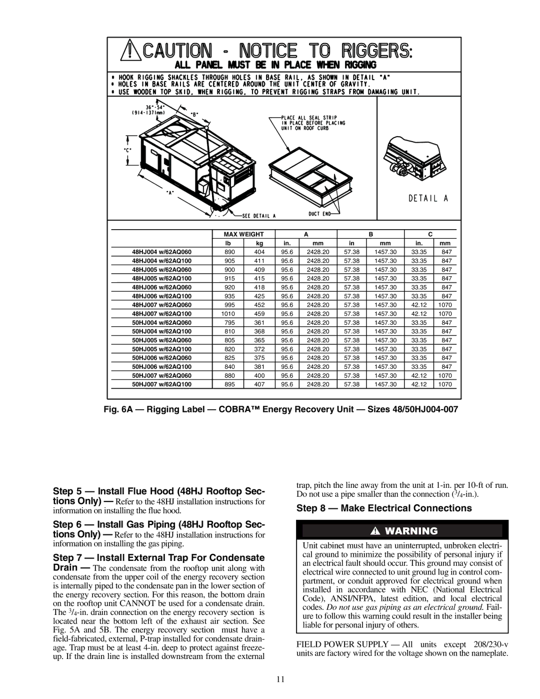
| MAX WEIGHT |
| A |
| B |
|
| C | ||
|
| lb | kg | in. | mm | in |
| mm | in. |
| mm |
48HJ004 w/62AQ060 | 890 | 404 | 95.6 | 2428.20 | 57.38 |
| 1457.30 | 33.35 |
| 847 | |
48HJ004 w/62AQ100 | 905 | 411 | 95.6 | 2428.20 | 57.38 |
| 1457.30 | 33.35 |
| 847 | |
48HJ005 w/62AQ060 | 900 | 409 | 95.6 | 2428.20 | 57.38 |
| 1457.30 | 33.35 |
| 847 | |
48HJ005 w/62AQ100 | 915 | 415 | 95.6 | 2428.20 | 57.38 |
| 1457.30 | 33.35 |
| 847 | |
48HJ006 w/62AQ060 | 920 | 418 | 95.6 | 2428.20 | 57.38 |
| 1457.30 | 33.35 |
| 847 | |
48HJ006 w/62AQ100 | 935 | 425 | 95.6 | 2428.20 | 57.38 |
| 1457.30 | 33.35 |
| 847 | |
48HJ007 w/62AQ060 | 995 | 452 | 95.6 | 2428.20 | 57.38 |
| 1457.30 | 42.12 |
| 1070 | |
48HJ007 w/62AQ100 | 1010 | 459 | 95.6 | 2428.20 | 57.38 |
| 1457.30 | 42.12 |
| 1070 | |
50HJ004 w/62AQ060 | 795 | 361 | 95.6 | 2428.20 | 57.38 |
| 1457.30 | 33.35 |
| 847 | |
50HJ004 w/62AQ100 | 810 | 368 | 95.6 | 2428.20 | 57.38 |
| 1457.30 | 33.35 |
| 847 | |
50HJ005 w/62AQ060 | 805 | 365 | 95.6 | 2428.20 | 57.38 |
| 1457.30 | 33.35 |
| 847 | |
50HJ005 w/62AQ100 | 820 | 372 | 95.6 | 2428.20 | 57.38 |
| 1457.30 | 33.35 |
| 847 | |
50HJ006 w/62AQ060 | 825 | 375 | 95.6 | 2428.20 | 57.38 |
| 1457.30 | 33.35 |
| 847 | |
50HJ006 w/62AQ100 | 840 | 381 | 95.6 | 2428.20 | 57.38 |
| 1457.30 | 33.35 |
| 847 | |
50HJ007 w/62AQ060 | 880 | 400 | 95.6 | 2428.20 | 57.38 |
| 1457.30 | 42.12 |
| 1070 | |
50HJ007 w/62AQ100 | 895 | 407 | 95.6 | 2428.20 | 57.38 |
| 1457.30 | 42.12 |
| 1070 | |
Fig. 6A — Rigging Label — COBRA™ Energy Recovery Unit — Sizes 48/50HJ004-007
Step 5 — Install Flue Hood (48HJ Rooftop Sec- tions Only) — Refer to the 48HJ installation instructions for information on installing the flue hood.
Step 6 — Install Gas Piping (48HJ Rooftop Sec- tions Only) — Refer to the 48HJ installation instructions for information on installing the gas piping.
Step 7 — Install External Trap For Condensate Drain — The condensate from the rooftop unit along with condensate from the upper coil of the energy recovery section is internally piped to the condensate pan in the lower section of the energy recovery section. For this reason, the bottom drain on the rooftop unit CANNOT be used for a condensate drain. The
trap, pitch the line away from the unit at
Step 8 — Make Electrical Connections
Unit cabinet must have an uninterrupted, unbroken electri- cal ground to minimize the possibility of personal injury if an electrical fault should occur. This ground may consist of electrical wire connected to unit ground lug in control com- partment, or conduit approved for electrical ground when installed in accordance with NEC (National Electrical Code), ANSI/NFPA, latest edition, and local electrical codes. Do not use gas piping as an electrical ground. Fail- ure to follow this warning could result in the installer being liable for personal injury of others.
FIELD POWER SUPPLY — All units except
11