FOR MOISTUREMI$ER UNITS ONLY
LIGHT
COMMERCIAL
THERMIDISTAT
ACCESSORY
62AQ
CONNECTION BOARD
OPTIONAL
HUMIDISTAT (HL38MG029)
Fig. 8 — Light Commercial Thermidistat Accessory Low-Voltage Connections
Step 9 — Assemble and Mount
NOTE: Mount the hood sides to the energy recovery section first, and then the hood top for easier installation. The ther- mostats are shipped
1. | Assemble and mount supply air hood as shown in Fig. 11. |
2. | Discard the tape that holds the thermostats behind the |
| damper plates. Mount thermostats to the hood sides of the |
| energy recovery section unit into the holes provided, with |
| thermostat terminals facing up. See Fig. 11. Mount out- |
| side cooling set point thermostat part number |
| HH22HA060 (white label) on the left side of the hood. |
| See Fig. 11. |
3. | Mount the outside heating thermostat part number |
| HH22HA065 (red label) on the right side of the hood. See |
| Fig. 11. |
4. | From the outside of the unit’s side panels fasten the |
| thermostat(s) with two mounting screws, with the quick |
| connect terminals face up. See Fig. 11. |
5. | Install thermostat knobs (provided in kit). See Fig. 11. |
6. | Set supply air quantity (on units with optional factory- |
| installed supply air fan [GA] or |
| supply air fan kit |
| fan speed and damper position to obtain desired cfm. |
| Relocate damper stops to the desired position on the |
DDC CONTROL CONNECTION
TB3 BOARD
R24 VAC G RMTOCC
CMPSAFE
Y2 FSD
W1 SFS
NOT USED
CC X X
TB1
R
![]() Y1
Y1
Y2
W1
W2
G
C
X
R
![]() Y1
Y1
Y2
W1
W2
G
C
damper support rail and adjust the fan speed by relocating |
the wire on the supply fan motor terminal block. Factory |
set position is 45 degrees for the damper position, and |
medium speed for the motor. Relocate stops to top hole |
for 30 degrees, bottom hole for 60 degrees, and remove |
stops for 90 degrees (see Fig. 11). |
7. Install the aluminum filter screen and end cap with |
screws along the top, as shown in Fig. 11. |
Step 10 — Mount the Barometric Relief Damper — The hood kit supplied with the energy recovery section is needed to complete this installation. The exhaust air hood (that includes the barometric relief damper) must be
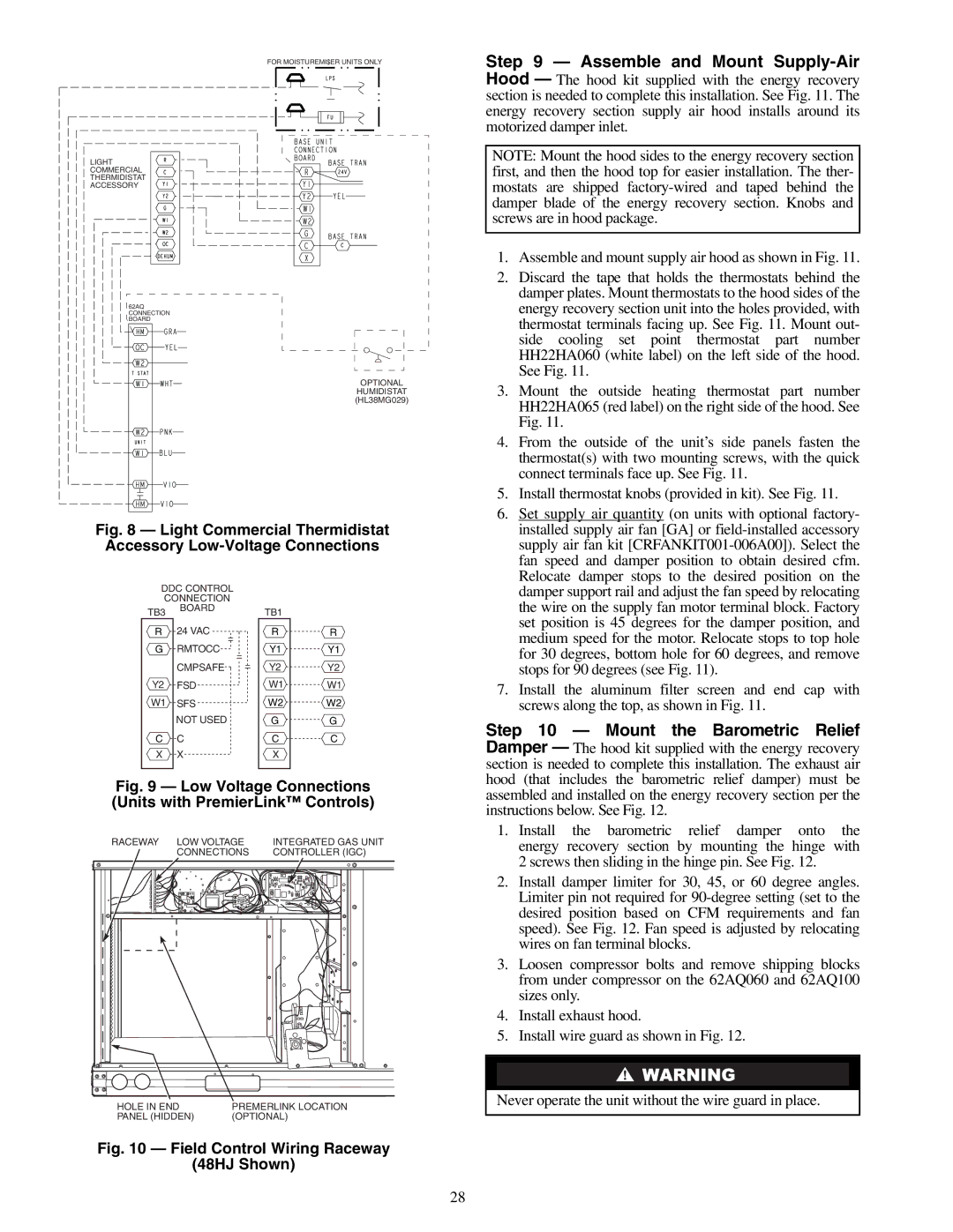
Fig. 9 — Low Voltage Connections (Units with PremierLink™ Controls)
RACEWAY LOW VOLTAGE | INTEGRATED GAS UNIT | |||||||||||||||
| CONNECTIONS | CONTROLLER (IGC) | ||||||||||||||
|
|
|
|
|
|
|
|
|
|
|
|
|
|
|
|
|
|
|
|
|
|
|
|
|
|
|
|
|
|
|
|
|
|
|
|
|
|
|
|
|
|
|
|
|
|
|
|
|
|
|
|
|
|
|
|
|
|
|
|
|
|
|
|
|
|
|
|
|
|
|
|
|
|
|
|
|
|
|
|
|
|
|
|
|
|
|
|
|
|
|
|
|
|
|
|
|
|
|
|
|
|
|
|
|
|
|
|
|
|
|
|
|
|
|
|
|
|
|
|
|
|
|
|
|
|
|
|
|
|
|
|
|
|
|
|
|
|
|
|
|
|
|
|
|
|
|
|
|
|
|
|
|
|
|
|
|
|
|
|
|
|
|
|
|
|
|
|
|
|
|
|
|
|
|
|
|
|
|
|
|
|
|
|
|
|
|
|
|
|
|
|
|
|
|
|
|
|
|
|
|
|
|
|
|
|
|
|
|
|
|
|
|
|
|
|
|
|
|
|
|
|
|
|
|
|
|
|
|
|
|
|
|
|
|
|
|
|
|
|
|
|
|
|
|
|
|
|
|
|
|
|
|
|
|
|
|
|
|
|
|
|
|
|
|
|
|
|
|
|
|
|
HOLE IN END | PREMERLINK LOCATION |
PANEL (HIDDEN) | (OPTIONAL) |
Fig. 10 — Field Control Wiring Raceway
(48HJ Shown)
assembled and installed on the energy recovery section per the instructions below. See Fig. 12.
1.Install the barometric relief damper onto the energy recovery section by mounting the hinge with 2 screws then sliding in the hinge pin. See Fig. 12.
2.Install damper limiter for 30, 45, or 60 degree angles. Limiter pin not required for
3.Loosen compressor bolts and remove shipping blocks from under compressor on the 62AQ060 and 62AQ100 sizes only.
4.Install exhaust hood.
5.Install wire guard as shown in Fig. 12.
Never operate the unit without the wire guard in place.
28