Step 11 — Set the Outdoor Cooling and Heat- ing Thermostats
IMPORTANT: The energy recovery section unit is shipped with an outdoor thermostat set at 55 F which locks out mechanical cooling on the RTU (rooftop unit) and the energy recovery section compressor. If this feature is not desirable, the rooftop unit’s compressor can be allowed to run by relocating both gray wires to the same side of the Low Temperature Lockout Thermostat (LTLO) leaving the white wire on the opposite pole, locking out only the energy recovery section compressor. The LTLO is also accessible by removing the filter access panel and the door of the damper mounting bracket. Refer to Troubleshooting section.
COOLING — During the unoccupied period, the economizer mode of operation is used as the first stage of cooling. When the outside air temperature is below the cooling thermostat set point, the outside air will be used for first stage cooling.
HEATING — The heating thermostat should be adjusted to the second stage balance point (heat output of the energy re- covery section plus the heat output of the first stage on rooftop unit equals building load at this temperature). Above this set- ting, first stage heating will be the energy recovery section unit and second stage will be the first stage of the rooftop unit. Below this point first stage heating will be the energy recovery section unit plus first stage heating of the rooftop unit. The sec- ond stage will be the second stage of the rooftop unit.
HOOD TOP | DAMPER BLADE STOP |
| SHIPPED WITH UNIT |
KNOB | IN 45° POSITION |
SCREWS (2) |
|
HOOD |
|
SIDE |
|
| LTLO |
| MOUNTING |
| BRACKET |
END CAP | HEATING POINT |
THERMOSTAT |
| (RED LABEL) |
|
COOLING SET POINT |
|
|
THERMOSTAT (WHITE LABEL) |
| TEMPERATURE |
|
| |
|
| COOLING |
TEMPERATURE SWITCH | HOOD SIDE | LOCKOUT (LTLO) |
| ||
|
| |
SHIPPED WITH UNIT | SCREW INSTALLATION (2) | |
| ||
| KNOB |
|
ALUMINUM FILTER SCREEN |
|
|
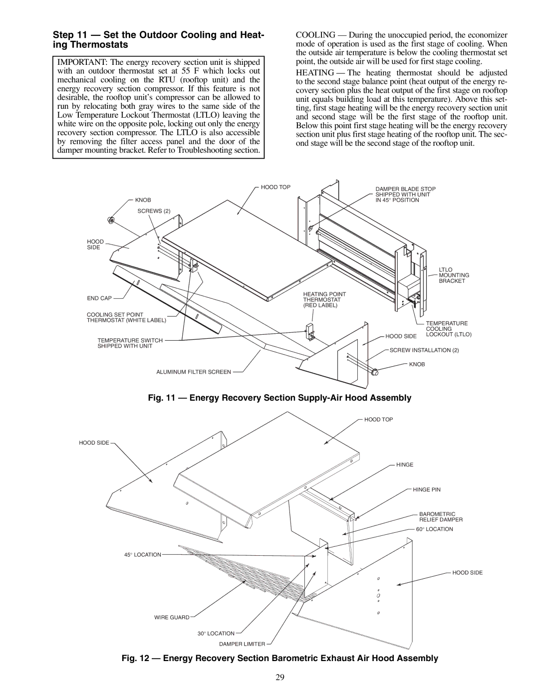
Fig. 11 — Energy Recovery Section Supply-Air Hood Assembly
HOOD TOP
HOOD SIDE
HINGE
HINGE PIN
BAROMETRIC
RELIEF DAMPER
60° LOCATION
45° LOCATION![]()
HOOD SIDE
WIRE GUARD
30° LOCATION
DAMPER LIMITER
Fig. 12 — Energy Recovery Section Barometric Exhaust Air Hood Assembly
29