Manuals
/
Carrier
/
Household Appliance
/
Air Conditioner
Carrier
48HJD005-007
specifications
Durablade Economizer Barometric, Relief Damper Characteristics
Models:
48HJD005-007
1
15
48
48
Download
48 pages
50.36 Kb
12
13
14
15
16
17
18
19
Troubleshooting
Relief Damper Characteristics
Install
Wiring Harness
Spark Gap Adjustment
Single-Phase Units
Service
Page 15
Image 15
Page 14
Page 16
Page 15
Image 15
Page 14
Page 16
Contents
Step 1 - Provide Unit Support
CONTENTS
SAFETY CONSIDERATIONS
INSTALLATION
1′-4″
Fig. 1 - Roof Curb Details
Fig. 3 - Condensate Drain Pan
Fig. 2 - Unit Leveling Tolerances
Step 7 - Make Electrical Connections
Table 1 - Physical Data
Table 1 - Physical Data cont
Fig. 5 - Base Unit Dimensions - 48HJ004-007
1/2″
3/4″
Fig. 6 - Flue Hood Details
Step 8 - Adjust Factory-Installed Options
Fig. 7 - Gas Piping Guide With Accessory
Thru-the-Curb Service Connections
Fig. 8 - Power Wiring Connections
Fig. 10 - Field Control Wiring Raceway
Fig. 9 - Low-Voltage Connections With or Without Economizer
Never operate a motor where a phase imbalance in supply volt
age is greater than 2%. Use the following formula to determine
the percent of voltage imbalance
Table 2C - 48HJ High-Static Motor Units Without Electrical Convenience Outlet
208/230-V Unit Shown
Fig. 11 - Accessory Field-Installed Humidistat
Fig. 14 - Outdoor-Air Hood Details
Fig. 13 - Typical Access Panel Locations
Fig. 15 - Durablade Economizer Installed in Unit
Fig. 16 - Horizontal Durablade Economizer Installation
Fig. 20 - Outdoor-Air Thermostat Enthalpy Control Installation
Wiring Harness
Fig. 19A - Durablade Economizer Damper Minimum Position Setting
Fig. 19B - Durablade Economizer Minimum Position Damper Setting
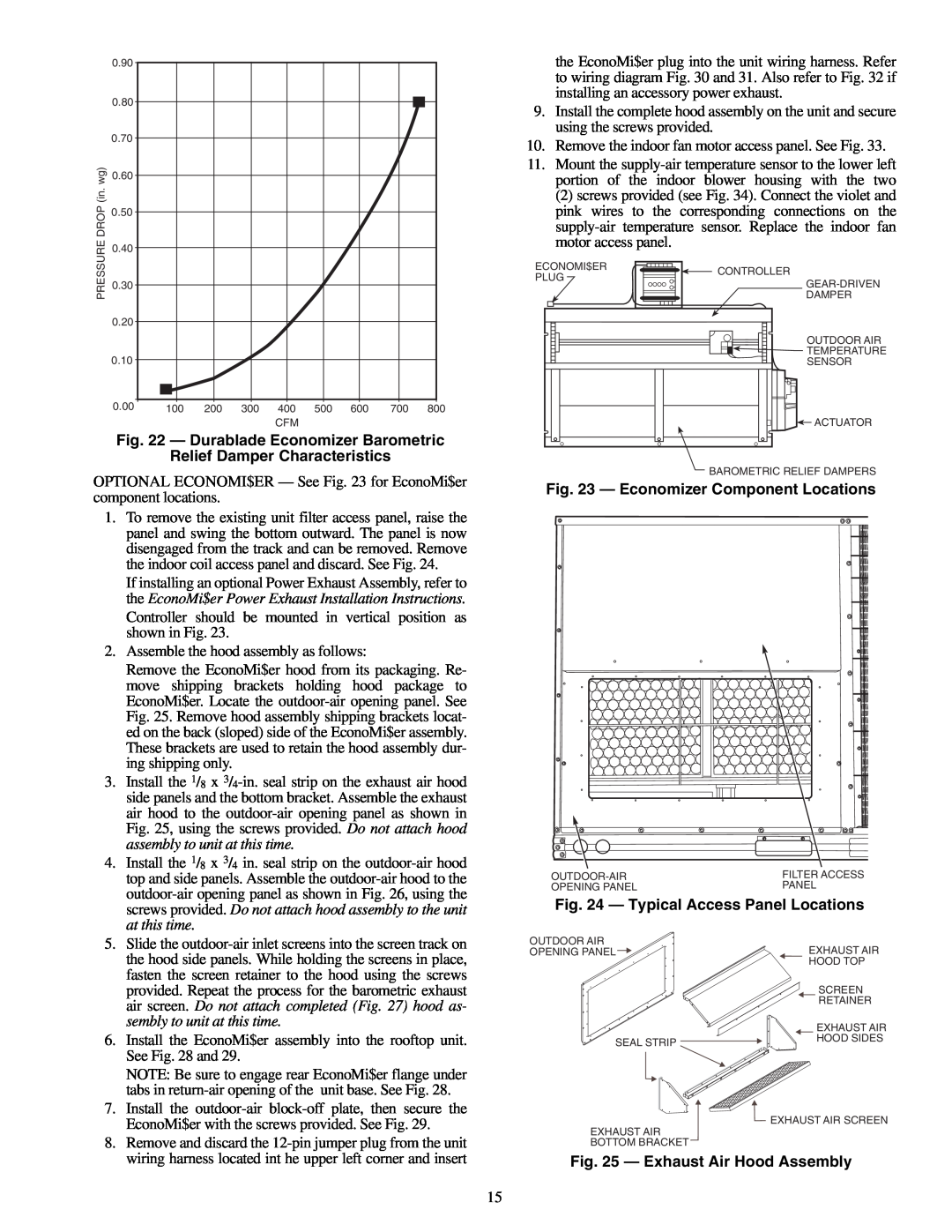
Fig. 22 - Durablade Economizer Barometric
Relief Damper Characteristics
Fig. 24 - Typical Access Panel Locations
Fig. 25 - Exhaust Air Hood Assembly
Fig. 29 - EconoMi$er Installed
Fig. 28 - Rear EconoMi$er Flange Installation
Fig. 26 - Outdoor-Air Hood Assembly
Fig. 27 - Completed Hood Assembly
POWER EXHAUST SYSTEM HIGH VOLTAGE
Fig. 31 - EconoMi$er Sensor Wiring
Fig. 33 - Typical Access Panel Locations
Fig. 32 - Wiring Diagram for Power Exhaust System
Potentiometers Factory Settings
Fig. 34 - Supply-Air Sensor Placement
Table 4 - Default Potentiometer Settings
Fig. 35 - EconoMi$er Control Adjustment
Step 9 - Adjust Evaporator-Fan Speed - Ad
Fig. 38 - Evaporator-Fan Pulley Adjustment
Fig. 37 - Belt-Drive Motor Mounting
Table 5A - 48HJ Fan Rpm at Motor Pulley Setting With Standard Motor
Table 6 - Evaporator-Fan Motor Data - Standard Motor
Table 7 - Evaporator-Fan Motor Data - High-Static Motors
Table 8 - Motor Nominal Horsepower
Table 9 - Outdoor Sound Power Total Unit
Bels
Table 12 - 48HJ005 Fan Performance - Vertical Discharge Units With Standard Motor
3-Phase Units
Single-Phase Units
Table 16 - 48HJ007 Fan Performance - Vertical Discharge Units With Standard Motor
Table 18 - 48HJ004 Fan Performance - Horizontal Discharge Units With Standard Motor
Table 20 - 48HJ005 Fan Performance - Horizontal Discharge Units With Standard Motor
3-Phase Units
Package Static Pressure Drop in. wg
FIOP - Factory-Installed Option
Table 26 - Economizer Static Pressure Drop in. wg
Table 27 - FIOP MoistureMiser Dehumidification
START-UP
PRE-START-UP
Heating
Operating Sequence
Table 28 - Altitude Compensation
When the supply-air temperature falls between 57 F and
Fig. 39 - MoistureMiser Option Operation
Fig. 42 - Separating Coil Sections
SERVICE
Lubrication
Fig. 40 - Cleaning Condenser Coil Fig. 41 - Propping Up Top Panel
Fig. 43 - Condenser-Fan Adjustment
Fig. 44 - Cooling Charging Chart Standard 48HJ004
Fig. 45 - Cooling Charging Chart Standard 48HJ005
Fig. 47 - Cooling Charging Chart Standard 48HJ007
Fig. 46 - Cooling Charging Chart Standard 48HJ006
Fig. 48 - Cooling Charging Chart, 48HJ004 with Optional MoistureMiser Dehumidification Package
Fig. 52 - Burner Section Details Fig. 53 - Burner Tray Details
Table 29 - LED Error Code Description
48HJF005-007 - 150,000 BTUH INPUT
Fig. 54 - Spark Gap Adjustment
LOW HEAT 48HJE004, 48HJD005-007 - 72,000 BTUH INPUT
MEDIUM AND HIGH HEAT 48HJE005-007, 48HJF004 - 115,000 BTUH INPUT
Table 30 - LED Error Code Service Analysis
TROUBLESHOOTING
Table 32 - Durablade Economizer Service Analysis
Table 31 - Heating Service Analysis
Table 34 - EconoMi$er Troubleshooting
Table 33 - EconoMi$er Flash Code Identification
Critical
Table 35 - MoistureMiser Dehumidification Subcooler Service Analysis
Compressor operates continuously
Table 36 - Cooling Service Analysis
208/230 3-Phase Unit Shown
Fig. 55 - Typical Wiring Schematic and Component Arrangement
NOTES FOR FIG
LEGEND AND NOTES FOR FIG
Replaces 48HJ-17SI
Page
III. START-UP
START-UP CHECKLIST Remove and Store in Job File
I. PRELIMINARY INFORMATION
II. PRE-START-UP insert checkmark in box as each item is completed
Top
Page
Image
Contents