(Text continued from page 13)
Unstable operation may occur when the gas valve and manifold assembly are forced out of position while connecting
If a ¯exible conductor is required or allowed by the authority having jurisdiction, black iron pipe shall be installed at the gas valve and shall extend a mini- mum of 2 in. outside the unit casing.
Never use a match or other open ¯ame when check- ing for gas leaks. Never purge gas line into com- bustion chamber. Failure to follow this warning could result in an explosion causing personal injury or death.
8.Check for gas leaks at the
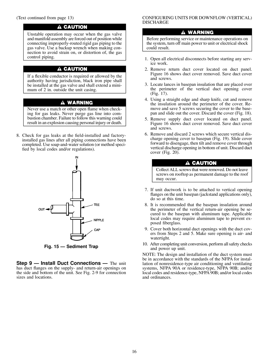
Fig. 15 Ð Sediment Trap
Step 9 Ð Install Duct Connections Ð The unit has duct ¯anges on the supply- and
CONFIGURING UNITS FOR DOWNFLOW (VERTICAL) DISCHARGE
Before performing service or maintenance operations on the system, turn off main power to unit or electrical shock could result.
1.Open all electrical disconnects before starting any serv- ice work.
2.Remove return duct cover located on duct panel. Figure 16 shows duct cover removed. Save duct cover and screws.
3.Locate lances in basepan insulation that are placed over the perimeter of the vertical duct opening cover (Fig. 17).
4.Using a straight edge and sharp knife, cut and remove the insulation around the perimeter of the cover. Re- move and save 5 screws securing the cover to the base- pan and slide out the cover. Discard the cover (Fig. 18).
5.Remove supply duct cover located on duct panel. Figure 16 shows duct cover removed. Save duct cover and screws.
6.Remove and discard 2 screws which secure vertical dis- charge opening cover to basepan (Fig. 19). Slide cover forward to disengage, then tilt and remove cover through vertical discharge opening in bottom of unit. Discard duct cover (Fig. 20).
Collect ALL screws that were removed. Do not leave screws on rooftop as permanent damage to the roof may occur.
7.If unit ductwork is to be attached to vertical opening ¯anges on the unit basepan (jackstand applications only), do so at this time.
8.It is recommended that the basepan insulation around the perimeter of the vertical
9.Cover both horizontal duct openings with the duct cov- ers from Steps 2 and 5. Make sure opening is air- and watertight.
10.After completing unit conversion, perform all safety checks and power up unit.
NOTE: The design and installation of the duct system must be in accordance with the standards of the NFPA for instal- lation of
16