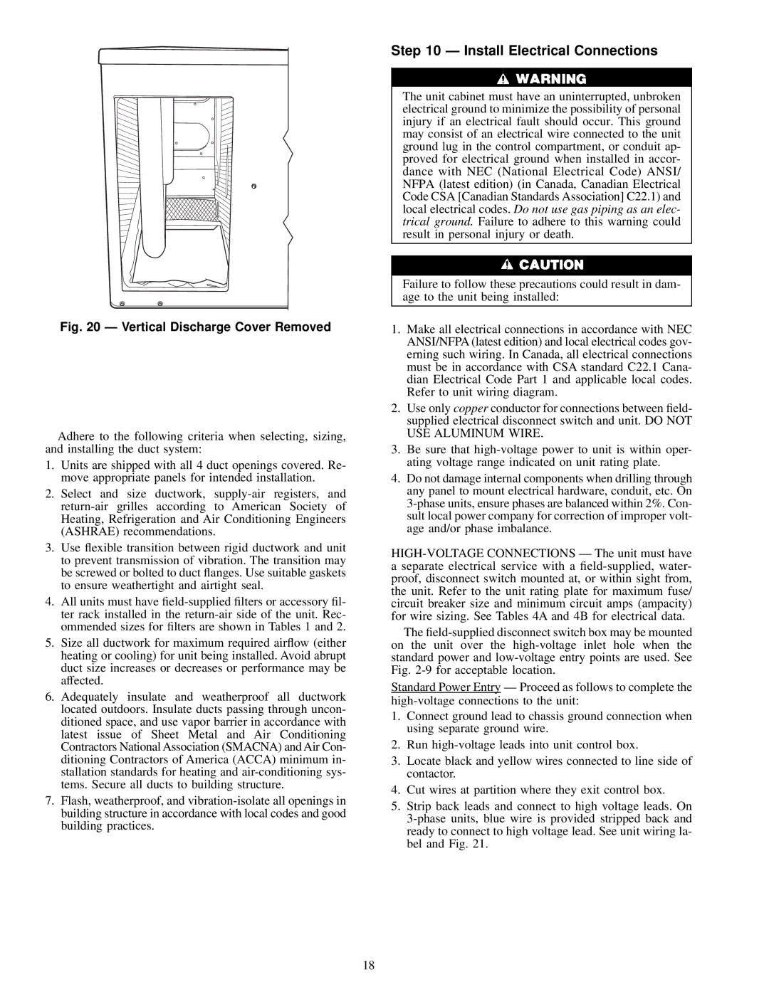
Fig. 20 Ð Vertical Discharge Cover Removed
Adhere to the following criteria when selecting, sizing, and installing the duct system:
1.Units are shipped with all 4 duct openings covered. Re- move appropriate panels for intended installation.
2.Select and size ductwork,
3.Use ¯exible transition between rigid ductwork and unit to prevent transmission of vibration. The transition may be screwed or bolted to duct ¯anges. Use suitable gaskets to ensure weathertight and airtight seal.
4.All units must have
5.Size all ductwork for maximum required air¯ow (either heating or cooling) for unit being installed. Avoid abrupt duct size increases or decreases or performance may be affected.
6.Adequately insulate and weatherproof all ductwork located outdoors. Insulate ducts passing through uncon- ditioned space, and use vapor barrier in accordance with latest issue of Sheet Metal and Air Conditioning Contractors National Association (SMACNA) and Air Con- ditioning Contractors of America (ACCA) minimum in- stallation standards for heating and
7.Flash, weatherproof, and
Step 10 Ð Install Electrical Connections
The unit cabinet must have an uninterrupted, unbroken electrical ground to minimize the possibility of personal injury if an electrical fault should occur. This ground may consist of an electrical wire connected to the unit ground lug in the control compartment, or conduit ap- proved for electrical ground when installed in accor- dance with NEC (National Electrical Code) ANSI/ NFPA (latest edition) (in Canada, Canadian Electrical Code CSA [Canadian Standards Association] C22.1) and local electrical codes. Do not use gas piping as an elec- trical ground. Failure to adhere to this warning could result in personal injury or death.
Failure to follow these precautions could result in dam- age to the unit being installed:
1.Make all electrical connections in accordance with NEC ANSI/NFPA (latest edition) and local electrical codes gov- erning such wiring. In Canada, all electrical connections must be in accordance with CSA standard C22.1 Cana- dian Electrical Code Part 1 and applicable local codes. Refer to unit wiring diagram.
2.Use only copper conductor for connections between ®eld- supplied electrical disconnect switch and unit. DO NOT USE ALUMINUM WIRE.
3.Be sure that
4.Do not damage internal components when drilling through any panel to mount electrical hardware, conduit, etc. On
aseparate electrical service with a
The
Standard Power Entry Ð Proceed as follows to complete the
1.Connect ground lead to chassis ground connection when using separate ground wire.
2.Run
3.Locate black and yellow wires connected to line side of contactor.
4.Cut wires at partition where they exit control box.
5.Strip back leads and connect to high voltage leads. On
18