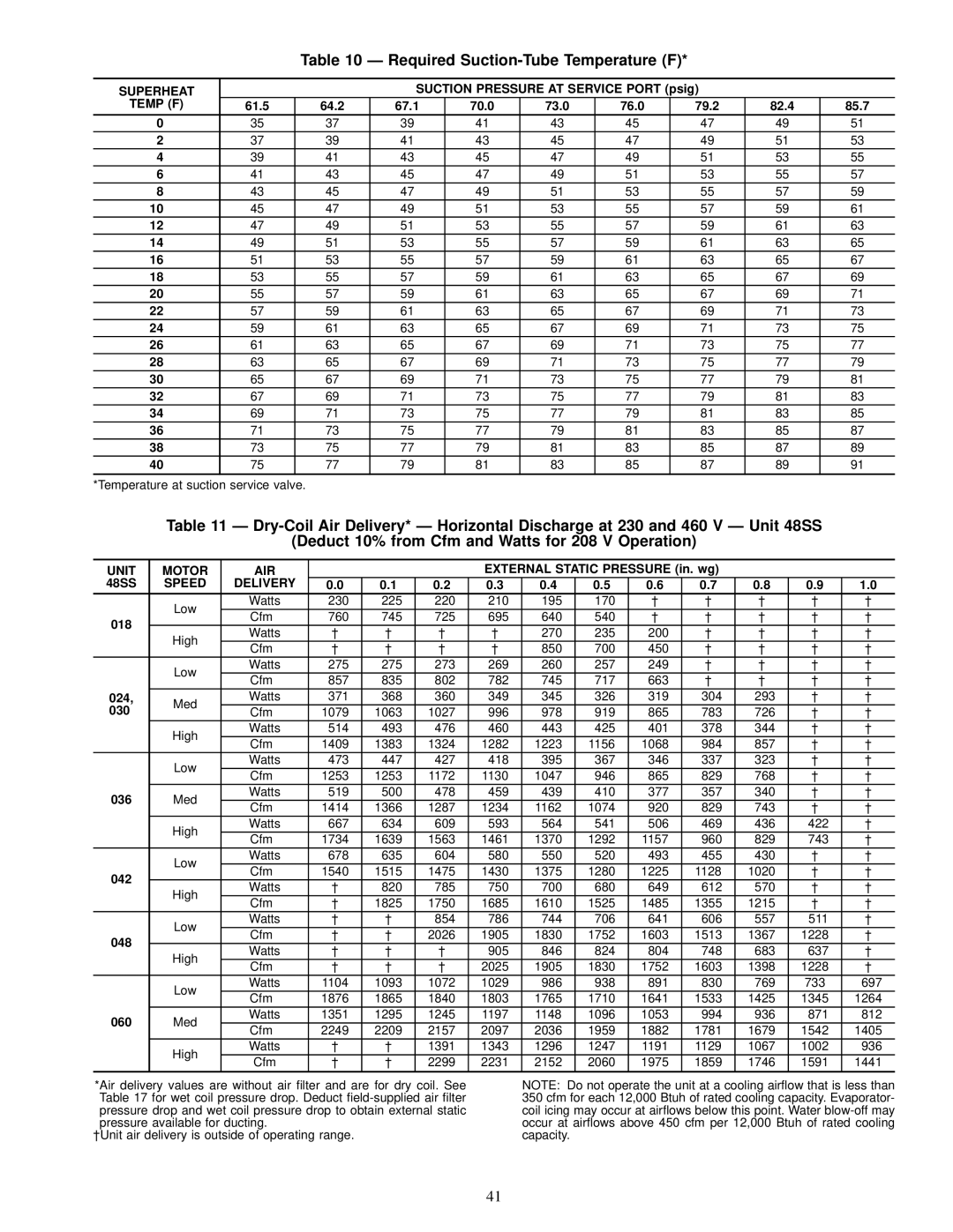
Table 10 Ð Required Suction-Tube Temperature (F)*
SUPERHEAT |
|
| SUCTION PRESSURE AT SERVICE PORT (psig) |
|
| ||||
TEMP (F) | 61.5 | 64.2 | 67.1 | 70.0 | 73.0 | 76.0 | 79.2 | 82.4 | 85.7 |
0 | 35 | 37 | 39 | 41 | 43 | 45 | 47 | 49 | 51 |
2 | 37 | 39 | 41 | 43 | 45 | 47 | 49 | 51 | 53 |
4 | 39 | 41 | 43 | 45 | 47 | 49 | 51 | 53 | 55 |
6 | 41 | 43 | 45 | 47 | 49 | 51 | 53 | 55 | 57 |
8 | 43 | 45 | 47 | 49 | 51 | 53 | 55 | 57 | 59 |
10 | 45 | 47 | 49 | 51 | 53 | 55 | 57 | 59 | 61 |
12 | 47 | 49 | 51 | 53 | 55 | 57 | 59 | 61 | 63 |
14 | 49 | 51 | 53 | 55 | 57 | 59 | 61 | 63 | 65 |
16 | 51 | 53 | 55 | 57 | 59 | 61 | 63 | 65 | 67 |
18 | 53 | 55 | 57 | 59 | 61 | 63 | 65 | 67 | 69 |
20 | 55 | 57 | 59 | 61 | 63 | 65 | 67 | 69 | 71 |
22 | 57 | 59 | 61 | 63 | 65 | 67 | 69 | 71 | 73 |
24 | 59 | 61 | 63 | 65 | 67 | 69 | 71 | 73 | 75 |
26 | 61 | 63 | 65 | 67 | 69 | 71 | 73 | 75 | 77 |
28 | 63 | 65 | 67 | 69 | 71 | 73 | 75 | 77 | 79 |
30 | 65 | 67 | 69 | 71 | 73 | 75 | 77 | 79 | 81 |
32 | 67 | 69 | 71 | 73 | 75 | 77 | 79 | 81 | 83 |
34 | 69 | 71 | 73 | 75 | 77 | 79 | 81 | 83 | 85 |
36 | 71 | 73 | 75 | 77 | 79 | 81 | 83 | 85 | 87 |
38 | 73 | 75 | 77 | 79 | 81 | 83 | 85 | 87 | 89 |
40 | 75 | 77 | 79 | 81 | 83 | 85 | 87 | 89 | 91 |
|
|
|
|
|
|
|
|
|
|
*Temperature at suction service valve.
Table 11 Ð
(Deduct 10% from Cfm and Watts for 208 V Operation)
UNIT | MOTOR | AIR |
|
|
| EXTERNAL STATIC PRESSURE (in. wg) |
|
|
|
| ||||
48SS | SPEED | DELIVERY | 0.0 | 0.1 | 0.2 | 0.3 | 0.4 | 0.5 | 0.6 | 0.7 | 0.8 | 0.9 |
| 1.0 |
| Low | Watts | 230 | 225 | 220 | 210 | 195 | 170 | ² | ² | ² | ² |
| ² |
018 | Cfm | 760 | 745 | 725 | 695 | 640 | 540 | ² | ² | ² | ² |
| ² | |
|
| |||||||||||||
High | Watts | ² | ² | ² | ² | 270 | 235 | 200 | ² | ² | ² |
| ² | |
|
| |||||||||||||
| Cfm | ² | ² | ² | ² | 850 | 700 | 450 | ² | ² | ² |
| ² | |
|
|
| ||||||||||||
| Low | Watts | 275 | 275 | 273 | 269 | 260 | 257 | 249 | ² | ² | ² |
| ² |
| Cfm | 857 | 835 | 802 | 782 | 745 | 717 | 663 | ² | ² | ² |
| ² | |
|
|
| ||||||||||||
024, | Med | Watts | 371 | 368 | 360 | 349 | 345 | 326 | 319 | 304 | 293 | ² |
| ² |
030 | Cfm | 1079 | 1063 | 1027 | 996 | 978 | 919 | 865 | 783 | 726 | ² |
| ² | |
|
| |||||||||||||
| High | Watts | 514 | 493 | 476 | 460 | 443 | 425 | 401 | 378 | 344 | ² |
| ² |
| Cfm | 1409 | 1383 | 1324 | 1282 | 1223 | 1156 | 1068 | 984 | 857 | ² |
| ² | |
|
|
| ||||||||||||
| Low | Watts | 473 | 447 | 427 | 418 | 395 | 367 | 346 | 337 | 323 | ² |
| ² |
| Cfm | 1253 | 1253 | 1172 | 1130 | 1047 | 946 | 865 | 829 | 768 | ² |
| ² | |
|
|
| ||||||||||||
036 | Med | Watts | 519 | 500 | 478 | 459 | 439 | 410 | 377 | 357 | 340 | ² |
| ² |
Cfm | 1414 | 1366 | 1287 | 1234 | 1162 | 1074 | 920 | 829 | 743 | ² |
| ² | ||
|
|
| ||||||||||||
| High | Watts | 667 | 634 | 609 | 593 | 564 | 541 | 506 | 469 | 436 | 422 |
| ² |
| Cfm | 1734 | 1639 | 1563 | 1461 | 1370 | 1292 | 1157 | 960 | 829 | 743 |
| ² | |
|
|
| ||||||||||||
| Low | Watts | 678 | 635 | 604 | 580 | 550 | 520 | 493 | 455 | 430 | ² |
| ² |
042 | Cfm | 1540 | 1515 | 1475 | 1430 | 1375 | 1280 | 1225 | 1128 | 1020 | ² |
| ² | |
|
| |||||||||||||
High | Watts | ² | 820 | 785 | 750 | 700 | 680 | 649 | 612 | 570 | ² |
| ² | |
|
| |||||||||||||
| Cfm | ² | 1825 | 1750 | 1685 | 1610 | 1525 | 1485 | 1355 | 1215 | ² |
| ² | |
|
|
| ||||||||||||
| Low | Watts | ² | ² | 854 | 786 | 744 | 706 | 641 | 606 | 557 | 511 |
| ² |
048 | Cfm | ² | ² | 2026 | 1905 | 1830 | 1752 | 1603 | 1513 | 1367 | 1228 |
| ² | |
|
| |||||||||||||
High | Watts | ² | ² | ² | 905 | 846 | 824 | 804 | 748 | 683 | 637 |
| ² | |
|
| |||||||||||||
| Cfm | ² | ² | ² | 2025 | 1905 | 1830 | 1752 | 1603 | 1398 | 1228 |
| ² | |
|
|
| ||||||||||||
| Low | Watts | 1104 | 1093 | 1072 | 1029 | 986 | 938 | 891 | 830 | 769 | 733 |
| 697 |
| Cfm | 1876 | 1865 | 1840 | 1803 | 1765 | 1710 | 1641 | 1533 | 1425 | 1345 |
| 1264 | |
|
|
| ||||||||||||
060 | Med | Watts | 1351 | 1295 | 1245 | 1197 | 1148 | 1096 | 1053 | 994 | 936 | 871 |
| 812 |
Cfm | 2249 | 2209 | 2157 | 2097 | 2036 | 1959 | 1882 | 1781 | 1679 | 1542 |
| 1405 | ||
|
|
| ||||||||||||
| High | Watts | ² | ² | 1391 | 1343 | 1296 | 1247 | 1191 | 1129 | 1067 | 1002 |
| 936 |
| Cfm | ² | ² | 2299 | 2231 | 2152 | 2060 | 1975 | 1859 | 1746 | 1591 |
| 1441 | |
|
|
| ||||||||||||
*Air delivery values are without air ®lter and are for dry coil. See Table 17 for wet coil pressure drop. Deduct
²Unit air delivery is outside of operating range.
NOTE: Do not operate the unit at a cooling air¯ow that is less than 350 cfm for each 12,000 Btuh of rated cooling capacity. Evaporator- coil icing may occur at air¯ows below this point. Water
41