Air Filter
Never operate the unit without a suitable air ®lter in the
Inspect air ®lter(s) at least once each month and replace
Unit Top Removal
NOTE: When performing maintenance or service proce- dures that require removal of the unit top, be sure to perform all of the routine maintenance procedures that require top removal, including: inspection of the heat exchanger area, coil inspection and cleaning, and condensate drain pan in- spection and cleaning.
Only quali®ed service personnel should perform mainte- nance and service procedures that require unit top removal. Refer to the following top removal procedures:
1.Turn off gas supply, then turn off electric power to unit.
2.Remove all screws that secure unit top, including screws around 4 sides and those on top that screw into internal divider panels. Save all screws.
3.Lift top from unit carefully. Set top on edge.
4.Carefully replace and secure unit top to unit, using screws removed in Step 2, when maintenance and/or service pro- cedures are completed. (Be sure to use original screws that have rubber washers to seal out water when securing top to internal divider panels.)
Evaporator Blower and Motor
NOTE: Motors without oilers are prelubricated. Do not at- tempt to lubricate these motors.
For longer life, operating economy, and continuing effi- ciency, clean accumulated dirt and grease from the blower wheel and motor annually.
Lubricate the motor every 5 years if the motor is used in- termittently (thermostat FAN switch in AUTO. position), or every 2 years if the motor is used continuously (thermostat FAN switch in ON position).
Turn off the gas supply, then disconnect and tag elec- trical power to the unit before cleaning and lubricating the blower motor and wheel. Failure to adhere to this warning could cause personal injury or death.
To clean and lubricate the blower motor and wheel:
1.Remove and disassemble blower assembly as follows:
a.Remove blower access door.
b.On standard
c.On all units remove blower assembly from unit. Re- move screws securing blower to gas partition and slide assembly out. Be careful not to tear insulation in blower compartment.
d.Ensure proper reassembly by marking blower wheel and motor in relation to blower housing before dis- assembly.
e.Loosen setscrew(s) that secures wheel to motor shaft, remove screws that secure motor mount brackets to
housing, and slide motor and motor mount out of housing.
2.Lubricate motor as follows:
a.Thoroughly clean all accumulations of dirt or grease from motor housing.
b.Remove dust caps or plugs from oil ports located at each end of motor.
c.Use a good grade of SAE 20 nondetergent motor oil and put one teaspoon (3¤16 oz. or 16 to 25 drops) in each oil port.
d.Allow time for oil to be absorbed by each bearing, then wipe excess oil from motor housing.
e.Replace dust caps or plugs in oil ports.
3.Remove and clean blower wheel as follows:
a.Ensure proper reassembly by marking wheel orientation.
b.Lift wheel from housing. When handling and/or clean- ing blower wheel, be sure not to disturb balance weights (clips) on blower wheel vanes.
c.Remove
d.Reassemble wheel into housing.
e.Reassemble motor into housing. Be sure setscrews are tightened on motor shaft ¯ats and not on round part of shaft.
f.Reinstall blower access door.
4.Restore electrical power, then gas supply to unit. Start unit and check for proper blower rotation and motor speeds during heating and cooling cycles.
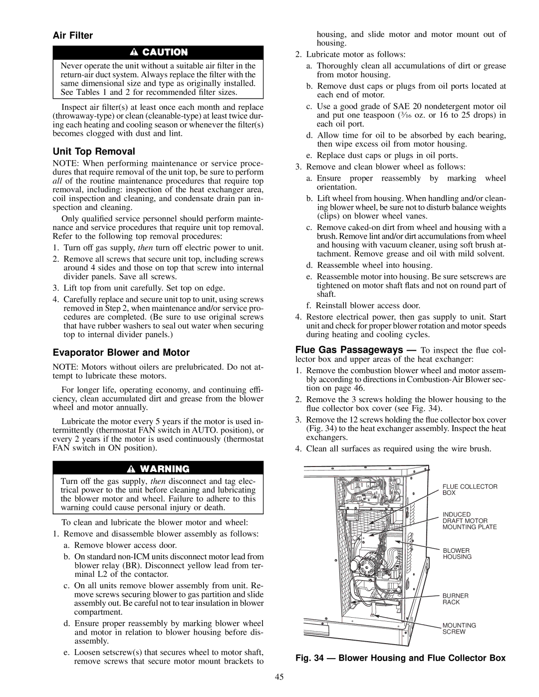
Flue Gas Passageways Ð To inspect the ¯ue col- lector box and upper areas of the heat exchanger:
1.Remove the combustion blower wheel and motor assem- bly according to directions in
2.Remove the 3 screws holding the blower housing to the ¯ue collector box cover (see Fig. 34).
3.Remove the 12 screws holding the ¯ue collector box cover (Fig. 34) to the heat exchanger assembly. Inspect the heat exchangers.
4.Clean all surfaces as required using the wire brush.
FLUE COLLECTOR
BOX
INDUCED
DRAFT MOTOR
MOUNTING PLATE
BLOWER
HOUSING
BURNER
RACK
![]() MOUNTING
MOUNTING
SCREW
Fig. 34 Ð Blower Housing and Flue Collector Box
45