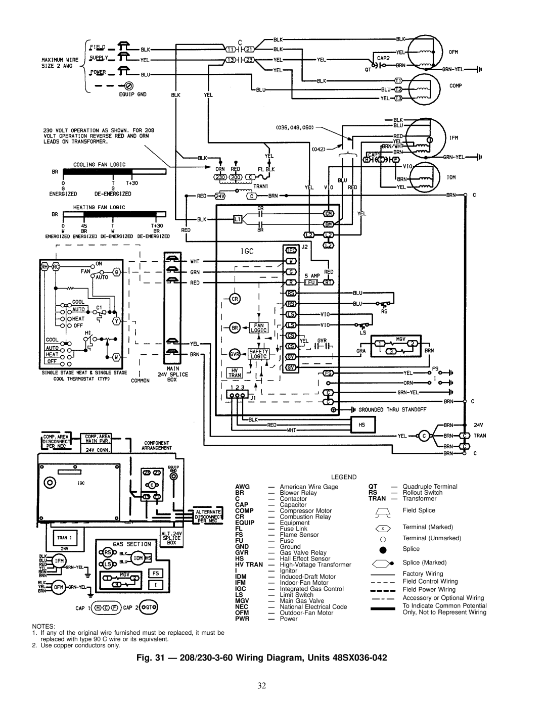
CONTENTS
SAFETY CONSIDERATIONS
Fig. 1 Ð Unit 48SX Shown With Optional Base Rail
Installation, Start-Upand Service Instructions
ELECTRICAL
REQD CLEARANCES FOR SERVICING. in. mm
ELECTRICAL
REQD CLEARANCES FOR SERVICING. in. mm
ELECTRICAL
REQD CLEARANCES FOR SERVICING. in. mm
ELECTRICAL
COND
RECEIVING AND INSTALLATION
Step 1 Ð Check Equipment
Step 2 Ð Provide Unit Support
Step 5 Ð Rig and Place Unit
CURB
Fig. 10 Ð Roof Curb Dimensions
PART NUMBER
Fig. 11 Ð Slab Mounting Details
Fig. 12 Ð Suggested Rigging for Units Without
Base Rail
Fig. 13 Ð Suggested Rigging for Units With
Step 6 Ð Connect Condensate Drain
Table 1 Ð Physical Data Ð Unit 48SS
Table 2 Ð Physical Data Ð Unit 48SX
Fig. 15 Ð Sediment Trap
Table 3 Ð Maximum Gas Flow Capacity
Fig. 16 Ð Supply and Return Duct Openings
Fig. 18 Ð Vertical Duct Cover Removed
Fig. 17 Ð Lance Location for Vertical Duct
Step 10 Ð Install Electrical Connections
Fig. 20 Ð Vertical Discharge Cover Removed
Table 4A Ð Electrical Data Ð Unit 48SS
Table 4B Ð Electrical Data Ð Unit 48SX
Fig. 21 Ð High- and Control-VoltageConnections
PRE-START-UP
Fig. 22 Ð Easy Select Interface Board
Fig. 23 Ð Fan Blade Clearance
Start Up Heating Section and Make Adjustments
START-UP
Fig. 24 Ð Burner Assembly
Fig. 25 Ð Monoport Burners
Start Up Cooling Section and Make Adjustments
Table 7 Ð LED Indications
Page
Page
Page
Page
Page
Page
Page
Page
CHECKING AND ADJUSTING REFRIGERANT CHARGE
EVAPORATOR AIRFLOW AND AIRFLOW ADJUSTMENTS
Proceed as follows
4.Measure and record the following
Table 8A Ð Superheat Charging Table, 48SS018
Table 8B Ð Superheat Charging Table, 48SS024
Table 8E Ð Superheat Charging Table, 48SS042
Table 8C Ð Superheat Charging Table, 48SS030
Table 8D Ð Superheat Charging Table, 48SS036
Table 8H Ð Superheat Charging Table, 48SS060
Table 9C Ð Superheat Charging Table, 48SX036
Table 9A Ð Superheat Charging Table, 48SX024
Table 9B Ð Superheat Charging Table, 48SX030
Table 9F Ð Superheat Charging Table, 48SX060
Table 9D Ð Superheat Charging Table, 48SX042
Table 9E Ð Superheat Charging Table, 48SX048
Table 10 Ð Required Suction-TubeTemperature F
Deduct 10% from Cfm and Watts for 208 V Operation
MAINTENANCE
Table 17 Ð Wet Coil Pressure Drop
Fig. 34 Ð Blower Housing and Flue Collector Box
Air Filter
Unit Top Removal
Evaporator Blower and Motor
Fig. 37 Ð Burner Rack Removed
Fig. 35 Ð Burner Access Panel
Fig. 36 Ð Removal of Motor and Blower Wheel
Condenser Coil, Evaporator Coil, and Conden
Condenser Fan
TROUBLESHOOTING
Cooling
Cooling cont
Heating
CALL FOR FREE CATALOG
SERVICE TRAINING
LED Troubleshooting Ð Error Code
Page
Remove and Store in Job File
I. PRELIMINARY INFORMATION
III. START-UP
ELECTRICAL