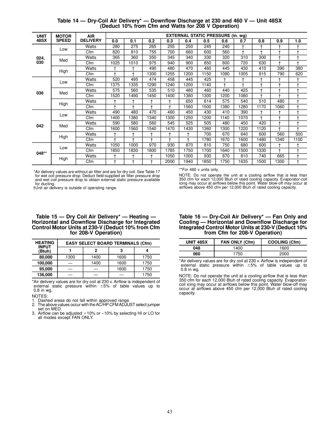
Table 14 Ð
(Deduct 10% from Cfm and Watts for 208 V Operation)
UNIT | MOTOR | AIR |
|
|
| EXTERNAL STATIC PRESSURE (in. wg) |
|
|
| |||||
48SX | SPEED | DELIVERY | 0.0 | 0.1 | 0.2 | 0.3 | 0.4 | 0.5 | 0.6 | 0.7 | 0.8 | 0.9 | 1.0 | |
| Low | Watts | 280 | 275 | 265 | 255 | 250 | 245 | 240 | ² | ² | ² | ² | |
| Cfm | 820 | 810 | 755 | 700 | 660 | 600 | 560 | ² | ² | ² | ² | ||
|
| |||||||||||||
024, | Med | Watts | 365 | 360 | 350 | 345 | 340 | 330 | 320 | 310 | 300 | ² | ² | |
030 | Cfm | 1025 | 1010 | 975 | 940 | 900 | 850 | 800 | 720 | 630 | ² | ² | ||
| ||||||||||||||
| High | Watts | ² | ² | 490 | 480 | 470 | 460 | 445 | 430 | 410 | 390 | 380 | |
| Cfm | ² | ² | 1300 | 1255 | 1200 | 1150 | 1080 | 1005 | 915 | 790 | 620 | ||
|
| |||||||||||||
| Low | Watts | 520 | 495 | 474 | 458 | 445 | 425 | ² | ² | ² | ² | ² | |
| Cfm | 1375 | 1335 | 1290 | 1240 | 1200 | 1140 | ² | ² | ² | ² | ² | ||
|
| |||||||||||||
036 | Med | Watts | 575 | 560 | 535 | 510 | 480 | 460 | 440 | 425 | ² | ² | ² | |
Cfm | 1520 | 1490 | 1450 | 1400 | 1380 | 1300 | 1200 | 1080 | ² | ² | ² | |||
|
| |||||||||||||
| High | Watts | ² | ² | ² | ² | 650 | 614 | 575 | 540 | 510 | 480 | ² | |
| Cfm | ² | ² | ² | ² | 1560 | 1500 | 1380 | 1280 | 1170 | 1060 | ² | ||
|
| |||||||||||||
| Low | Watts | 490 | 480 | 470 | 460 | 450 | 430 | 410 | 390 | ² | ² | ² | |
| Cfm | 1400 | 1380 | 1340 | 1300 | 1250 | 1200 | 1140 | 1070 | ² | ² | ² | ||
|
| |||||||||||||
042 | Med | Watts | 590 | 580 | 560 | 545 | 525 | 505 | 480 | 450 | 420 | ² | ² | |
Cfm | 1600 | 1560 | 1540 | 1470 | 1430 | 1360 | 1300 | 1220 | 1120 | ² | ² | |||
|
| |||||||||||||
| High | Watts | ² | ² | ² | ² | ² | 700 | 670 | 640 | 600 | 560 | 500 | |
| Cfm | ² | ² | ² | ² | ² | 1780 | 1670 | 1600 | 1480 | 1340 | 1100 | ||
|
| |||||||||||||
| Low | Watts | 1050 | 1000 | 970 | 930 | 870 | 810 | 750 | 680 | 600 | ² | ² | |
048** | Cfm | 1850 | 1830 | 1800 | 1785 | 1750 | 1700 | 1640 | 1500 | 1330 | ² | ² | ||
| ||||||||||||||
High | Watts | ² | ² | ² | 1050 | 1000 | 930 | 870 | 810 | 740 | 665 | ² | ||
| ||||||||||||||
| Cfm | ² | ² | ² | 2000 | 1940 | 1850 | 1750 | 1635 | 1500 | 1300 | ² | ||
|
| |||||||||||||
*Air delivery values are without air ®lter and are for dry coil. See Table 17 for wet coil pressure drop. Deduct
²Unit air delivery is outside of operating range.
**For 460 v units only.
NOTE: Do not operate the unit at a cooling air¯ow that is less than 350 cfm for each 12,000 Btuh of rated cooling capacity.
Table 15 Ð Dry Coil Air Delivery* Ð Heating Ð Horizontal and Down¯ow Discharge for Integrated Control Motor Units at
HEATING | EASY SELECT BOARD TERMINALS (Cfm) | |||
INPUT |
|
|
|
|
(Btuh) | 1 | 2 | 3 | 4 |
80,000 | 1300 | 1400 | 1600 | 1750 |
100,000 | Ð | 1400 | 1600 | 1750 |
95,000 | Ð | Ð | 1600 | 1750 |
136,000 | Ð | Ð | Ð | 1750 |
|
|
|
|
|
*Air delivery values are for dry coil at 230 v. Air¯ow is independent of external static pressure within 65% of table values up to 0.8 in wg.
NOTES:
1.Dashed areas do not fall within approved range.
2.The above values occur with the AC/HP CFM ADJUST select jumper set on MED.
3.Air¯ow can be adjusted110% or −10% by selecting HI or LO for all modes except FAN ONLY.
Table 16 Ð
UNIT 48SX | FAN ONLY (Cfm) | COOLING (Cfm) |
048 | 1400 | 1600 |
060 | 1750 | 2000 |
|
|
|
*Air delivery values are for dry coil at 230 v. Air¯ow is independent of external static pressure within 65% of table values up to 0.8 in wg.
NOTE: Do not operate the unit at a cooling air¯ow that is less than 350 cfm for each 12,000 Btuh of rated cooling capacity. Evaporator- coil icing may occur at air¯ows below this point. Water
43