when it starts. Also, no cooling will be produced at the evaporator. If any of these conditions occurs, refer to the Service section to correct the compressor rotation before continuing.
INTERNAL WIRING — Check all electrical connections in unit control boxes; tighten as required.
COMPRESSOR MOUNTING — Compressors are internal- ly spring mounted. Do not loosen or remove compressor hold- down bolts.
REFRIGERANT SERVICE PORTS — Each refrigerant system has a total of 2
CV Unit Start-Up
EVAPORATOR FAN — Fan belt and variable pitch motor pulleys are factory installed. See Tables
COOLING — Set the space thermostat to OFF position. Turn on unit power. Set space thermostat to COOL and the fan to AUTO. Adjust the thermostat temperature setting below room temperature. Compressor 1 starts on closure of contactor (com- pressors 1 and 2 on
Adjust the thermostat to an even lower setting until the ther- mostat energizes Y2 (the second cooling stage). Compressor 2 starts on closure of contactor (compressors 3 and 4 on
Adjust the thermostat temperature to a setting just below room temperature. The second stage of cooling should turn off.
Set the thermostat temperature above room temperature. All compressors and the unit fan should now be off.
HEATING (Heat Pump Units Only) — Follow the same se- quence as for cooling (above), except set the space thermostat to HEAT, and instead of adjusting the thermostat below room temperature, adjust it above. Verify that the compressors turn on and the unit runs in reverse cycle mode.
Set the thermostat below room temperature and confirm that the compressors and fan turn off.
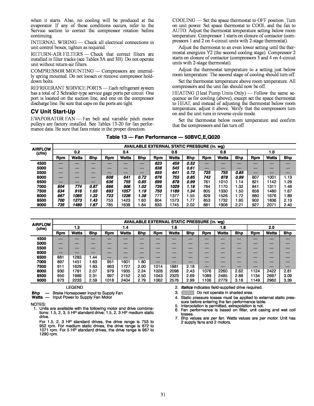
Table 13 — Fan Performance — 50BVC,E,Q020
AIRFLOW |
|
|
|
| AVAILABLE EXTERNAL STATIC PRESSURE (in. wg) |
|
|
|
| ||||||
| 0.2 |
|
| 0.4 |
|
| 0.6 |
|
| 0.8 |
|
| 1.0 |
| |
(cfm) |
|
|
|
|
|
|
|
|
|
| |||||
| Rpm | Watts | Bhp | Rpm | Watts | Bhp | Rpm | Watts | Bhp | Rpm | Watts | Bhp | Rpm | Watts | Bhp |
4500 | — | — | — | — | — | — | 623 | 459 | 0.52 | — | — | — | — | — | — |
5000 | — | — | — | — | — | — | 638 | 545 | 0.61 | — | — | — | — | — | — |
5500 | — | — | — | — | — | — | 655 | 641 | 0.72 | 725 | 755 | 0.85 | — | — | — |
6000 | — | — | — | 608 | 641 | 0.72 | 676 | 755 | 0.85 | 742 | 878 | 0.99 | 807 | 1001 | 1.13 |
6500 | — | — | — | 636 | 755 | 0.85 | 699 | 878 | 0.99 | 761 | 1010 | 1.14 | 821 | 1142 | 1.29 |
7000 | 604 | 774 | 0.87 | 666 | 906 | 1.02 | 726 | 1029 | 1.16 | 784 | 1170 | 1.32 | 841 | 1311 | 1.48 |
7500 | 634 | 916 | 1.03 | 693 | 1057 | 1.19 | 750 | 1189 | 1.34 | 805 | 1330 | 1.50 | 858 | 1480 | 1.67 |
8000 | 667 | 1085 | 1.22 | 723 | 1226 | 1.38 | 777 | 1377 | 1.55 | 829 | 1526 | 1.72 | 880 | 1676 | 1.89 |
8500 | 700 | 1273 | 1.43 | 753 | 1423 | 1.60 | 804 | 1573 | 1.77 | 853 | 1732 | 1.95 | 902 | 1836 | 2.13 |
9000 | 735 | 1480 | 1.67 | 785 | 1638 | 1.84 | 833 | 1745 | 2.02 | 881 | 1908 | 2.21 | 927 | 2071 | 2.40 |
|
|
|
|
|
|
|
|
|
|
|
|
|
|
|
|
AIRFLOW |
|
|
|
| AVAILABLE EXTERNAL STATIC PRESSURE (in. wg) |
|
|
|
| ||||||
| 1.2 |
|
| 1.4 |
|
| 1.6 |
|
| 1.8 |
|
| 2.0 |
| |
(cfm) |
|
|
|
|
|
|
|
|
|
| |||||
| Rpm | Watts | Bhp | Rpm | Watts | Bhp | Rpm | Watts | Bhp | Rpm | Watts | Bhp | Rpm | Watts | Bhp |
4500 | — | — | — | — | — | — | — | — | — | — | — | — | — | — | — |
5000 | — | — | — | — | — | — | — | — | — | — | — | — | — | — | — |
5500 | — | — | — | — | — | — | — | — | — | — | — | — | — | — | — |
6000 | — | — | — | — | — | — | — | — | — | — | — | — | — | — | — |
6500 | 881 | 1283 | 1.44 | — | — | — | — | — | — | — | — | — | — | — | — |
7000 | 897 | 1451 | 1.63 | 951 | 1601 | 1.80 | — | — | — | — | — | — | — | — | — |
7500 | 911 | 1629 | 1.83 | 963 | 1727 | 2.00 | 1014 | 1881 | 2.18 | — | — | — | — | — | — |
8000 | 930 | 1781 | 2.07 | 979 | 1935 | 2.24 | 1028 | 2098 | 2.43 | 1076 | 2260 | 2.62 | 1124 | 2422 | 2.81 |
8500 | 950 | 1989 | 2.31 | 997 | 2152 | 2.50 | 1043 | 2323 | 2.69 | 1089 | 2485 | 2.88 | 1134 | 2697 | 3.09 |
9000 | 973 | 2233 | 2.59 | 1018 | 2404 | 2.79 | 1062 | 2576 | 2.99 | 1106 | 2779 | 3.18 | 1149 | 2960 | 3.39 |
LEGEND
Bhp — Brake Horsepower Input to Supply Fan
Watts — Input Power to Supply Fan Motor
NOTES:
1.Units are available with the following motor and drive combina- tions: 1.5, 2, 3, 5 HP standard drive; 1.5, 2, 3 HP medium static drive.
For 1.5, 2, 3 HP standard drives, the drive range is 753 to 952 rpm. For medium static drives, the drive range is 872 to 1071 rpm. For 5 HP standard drives, the drive range is 967 to 1290 rpm.
2.Italics indicates
3.![]()
![]() Do not operate in shaded area.
Do not operate in shaded area.
4.Static pressure losses must be applied to external static pres- sure before entering the fan performance table.
5.Interpolation is permitted, extrapolation is not.
6.Fan performance is based on filter, unit casing and wet coil losses.
7.Bhp values are per fan. Watts values are per motor. Unit has 2 supply fans and 2 motors.
31